Temperature Influence on the Process of the Gelation of the Engine Oil by Liang Hong in Progress in Petrochemical Science_Journal of Petroleum Science and Engineering
Abstract
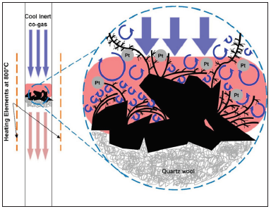
When a cool N2-CO2 co-gas stream flows over superheated activated carbon (AC) flakes, a vortex field near the interface is induced as a consequence of the confrontation of the cool co-gas stream and the hot vaporized carbon stream, where the pre-deposited Pt atom clusters on AC catalyze gasification of AC by CO2 to produce CO, and the CO undergoes immediate disproportionation to release carbon atoms in vapor form. The vortex field functions as a dynamic template for deposition of carbon vapor, leading to the proliferation of nano-sized carbon needles with characteristic spikes (ca. 1µm) and short in length through an anisotropic assembling of carbon atoms. A trace amount of Pt pre-coated on the AC flakes is sufficient to catalyze gasifying AC by CO2. This phenomenon is the first observation over the surface of amorphous carbon via catalytic pyrolysis without electric potential assistance.
Keywords: Nano carbon spines; Polypyrrole; HEC polymer; Raman spectra; Dendritic nano carbons; AC catalyze gasification; catalytic pyrolysis; Pt atom; CO gas treatment; Reverse boudouard reaction; AC flakes
Introduction
Dendritic growth is characterized by the presence of side branches that evolve under two different ways when the latent heat of fusion is removed from the interface [1]. Growth resulting from an undercooled melt (usually in alloys) results in equiaxed dendritic crystal formations when latent heat is dissipated through the cooler fluid at the interface whilst directional solidification or constrained growth results when the latent heat is dissipated swiftly.
This study unveils that the Pt atom clusters assist the generation of carbon atoms forming a vapor stream via a two-step reaction mechanism, which is responsible for the growth of dendritic dense carbon nanofibers from a porous carbon flakes. Such dendritic growth has been observed previously in cells [2-5], crystals [6,7] and metal alloys [8-13] with a characteristic tree-like structure, which is considered as the result of mass transfer under meta-stable thermodynamic state. Namely, the growth happens through a series of thermodynamic instabilities when the growth rate is limited by the rate of diffusion of solute atoms to the interface and the material is supercooled at the same time [14]. Dendrites have shapes that are most suitable for heat and mass transfers at small scales and hence, are highly attractive for applications seeking these properties. Numerous studies undertaken over the years offered the insights in dendritic growth of crystals [7], as well as mathematical models and simulations [6, 12-13,15-18] about the growth.
These growths are a result of faster material packing along energetically favorable crystallographic directions and may be due to anisotropy in the surface energy. In trying to minimize the area of these surfaces with the highest surface energy, the dendrite would exhibit a sharper and sharper tip as it grows [19]. When the crystallization front becomes morphologically unstable, small perturbations at the interface will lead to the formation of various polycrystalline structures, especially so for dendritic growth. The dendritic growth theory using Ivantsov transport theory relating to the dendrite tip radius and velocity of growth to the tip has been found to predict the growth rates and limitation of the existence of dendrites in 2D fairly accurately [1,14].
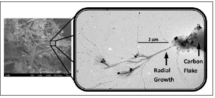
To the best of our knowledge, no reports or discussions on the dendritic carbon spinal growth in N2-CO2 co-gas atmosphere have been published nor observed before. Contrary to the growth of porous carbon fibers described explicitly in our previous work [20] caused by the random stacking of polyaromatic hydrocarbons (PAH) in the axial direction leading to the formation of fibers, this work proposes a different gowth path catalyzed by platinum atom clusters that assist with generation of CO via the reverse Boudouard reaction [21], which subsequently releases carbon atoms in vapor form that condense to form dense dendritic structures in the vortex field as illustrated in Figure 1. Although the incubation environment of this study is similar to that reported in [20], the resulting growth looks drastically different due to mediation by Pt atom clusters or colloids spread on the surface of the sample prior to the co-gas treatment. This paper aims to report and explain the growth mechanism we observed in detail.
Figure 1:
Experimental Procedure
Preparation of AC Flakes
An initial sample of 2-Hydroxyethyel cellulose (HEC) is carbonized by the method discussed elsewhere [22]. The resulting carbonaceous material from HEC was then activated at 700 oC under CO2 for 1 hour and cooled in an Ar purging stream. The carbon powder obtained was washed in water until the filtrate became colorless. This protocol resulted in an AC powder consisting of dense carbon flakes, which was used as the starting material for the preparation of the carbon needles.
Carbon Spinal Growth and Characterizations
Two separate, independent methods were employed to incorporate platinum onto the samples.
- Microwave approach: 0.2M Na2PtCl6.6H2O (Aldrich) was mixed with 0.2M SnCl2.2H2O (Aldrich) and 0.8M NaOH with ethylene glycol (Merck) and sonicated for 10 mins in an ultrasonic bath. The AC flakes (10g) was then added and the mixture sonicated for a further 10 minutes. Once this was complete, the mixture was placed in microwave and treated at high power for a minute and dried in a vacuum oven overnight [23]. The sample was subsequently treated at 800 °C under N2-CO2 co-gas atmosphere (50 cm3 min-1, 50 vol.% co-gas feed) for 5h to grow carbon needles.
- Sputtering approach: The AC flakes (10g) were coated with platinum via sputtering (JEOL JFC-1300 Auto Fine Coater, 90s, 30mA). The powder was then subjected to the N2-CO2 co-gas treatment as described above for 5h.
The final carbon samples obtained from both Pt-deposition methods were characterized by electron microscopy (JSM-6700F Field Emission Scanning Electron Microscope (FESEM), JEOL), Raman spectroscopy (Renishaw in Via Raman Microscope), and X-ray Diffraction (XRD, Bruker D8 Advance, Cu Ka radiation, l=1.54Å) using Cu target Ka-ray (40kV and 30mA) as X-ray source, respectively.
Result and Discussion
Formation of Dendritic Structures Over the Surface of AC Under Purge of CO-Gas
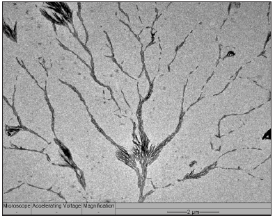
Under close examination using the transmission electron microscope (TEM), tree-like dendritic structures are observed to have formed from the sputtering coated AC specimen, with needle-like spinal growth sprouting forth from the “main vines” of the dendrites (Figure 2 & 3). Closer examination under a higher magnification reveals that these spines are dense and closely packed of different carbon blocks from base to tip (Figure 4). This type of growth is expected under supercooled condition, which presents itself when the elevated temperature at the Pt- deposited sites on AC (i.e. activated sites) comes into contact with the cool co-gas purge entering the reactor (Figure 1). During this process, Pt metal atom clusters deposited onto AC initiate conversion of PAH of AC to carbon atom species, which simultaneously experience a “supercooling effect” due to the contact with the entering co-gas stream. The tree-like dendritic needle structures start to grow in a specific radial direction due to the morphological instability [19] over the interface between AC and co-gas. The cool entering gas would form vortices upon reaching the region of superheated vaporized carbon species, leading to sporadic areas of cold fronts. The “supercooling effect” that takes place when these fronts meet therefore lead to the formation of the dendritic structure.
Figure 2: TEM image of dendrite produced by sputtered Pt; enlarged image of carbon spines (inset).
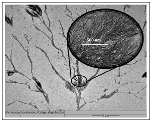
Figure 3: The tree-like growth from a main stem observed from the Pt sputtered AC flakes.
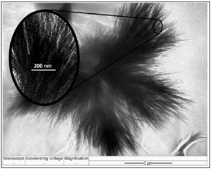
Figure 4: TEM image of a tip of a carbon spine.
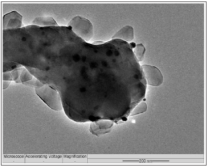
After a time of exposure, the platinum atom clusters were gradually converted to volatile carbonyl complexes in the CO atmosphere that vaporize and are removed together with effluent gas stream, thereby abruptly terminating the growth. This was verified by the EDS elemental analysis that showed no platinum content remained within the sample after the treatment was complete. Based on the observations from the micrograph in Figure 5, the treated sample displays dense, needle-like dendritic structures growing radially from the AC flakes in massive quantities; atom clustered around the surfaces of the flakes (Figure 5 magnified view). The needles were short, dense and thin, with no apparent pores on their surfaces. They are also split driven by crystallization [24]. Since the “supercooling” was limited only to the activated sites catalyzed by the platinum atom clusters, resulting in short ranged dendritic growth because the Pt atom clusters were likely vaporized before long in the form of carbonyl complexes.
Figure 5: Dense needle-like spines growing radially from the Pt-sputtered AC flake sample.
When the activated carbon is sputtered with platinum, most of the platinum atom cluster are miniature and uniformly spread over the surface of AC. It is found that the polymer precursor contributes significantly towards the development of the cactus-like structures with further branches growing outwardly from a main stem (Figure 2). A previous study done [22] by our group on the effects of HEC side chain groups on the final structure formed after carbonization and activation has shown the structural differences in PAH flakes, which would profoundly affect the final porous structures of the AC obtained. This phenomenon of similar dendritic growth had previously been observed in CO2-cyclopentane hydrates in solution [25] but neither in gaseous nor solid environments. Furthermore, an attempt to cultivate these fibers using polypyrrole as carbon source was unsuccessful due to a different PAH flake structure.
Formation of Carbon Spinal Structures
It is noteworthy that although similar dendritic growth resulted under both Pt-deposition conditions, growth of carbon needle-like spines could only be resulted from the sputtering approach. On the contrary, the microwave approach laid a less uniform covering of Pt colloids on AC and hence resulted coarse dendritic tree structure (Figure 6) due to dilute nucleation spots. The discussion, therefore, focuses the incubation of the Pt-sputtered sample.
Figure 6: The tree-like growth on the AC flakes prepared by the microwave-aided deposition approach.
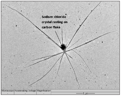
When scrutinizing the dark dots seen in the micrograph (Figure 5), it is a sodium chloride crystal resting on a small carbon center and not a platinum particle. Interestingly, it was apparent the branch-like dendritic structures exhibiting carbon needle-like outward growth originated from the activated flakes that the NaCl grains rested upon (Figure 7). The NaCl was known to leave behind from HEC polymer and, more importantly, this observation supports the view that PAH of AC were etched by CO2 mediated by the Pt atom clusters, namely, this gasification of AC concentrates NaCl distributing in AC simultaneously. Therefore, each NaCl grains represents a Pt-catalyzing gasification site. These sites occurred across the whole sample, but growth stopped a short distance radially away from the flakes (Figure 5). These NaCl grains hence label the original locations of Pt atom clusters before they were eventually vaporized as carbonyl complexes, terminating the growth of dendritic needles.
Figure 7: Carbon spines growing radially from a carbon flake center.
Besides, the surface analysis performed on the incubated sample shows a surface area of 951m2/g with pore volume of ca. 0.4cm3/g of sample. This concurs with our previous observation [20] that a larger surface area gained, compared to AC flake, can be attributed to the growth of needles whilst it is dense and hence, has a lower pore volume. Moreover, to understand whether the polymer precursor of AC affects dendric growth, glucose polymer and polypyrrole were in place of HEC, respectively, as the precursor for the AC flakes. The results were highly encouraging as thick, dense fibers were observed to grow on the surface of the AC flakes from the glucose polymer. However, no any spine was found on the polypyrrole-based AC flakes possibly due to a lack of oxygenated groups, which are present abundantly in AC prepared from glucose polymer as well as HEC.
Structural Characteristics of the Carbon Spines
We then used XRD method to examine possible crystalline structures of all the samples related to this study (Figure 8). It includes the following information:
Figure 8: XRD plot comparing the various samples related to this study. The x sign labels the crystalline NaCl phase.
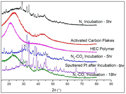
- HEC polymer (pink) and AC flakes (red) are amorphous;
- Incubation without Pt-coating under different atmospheres: N2 (black) and co-gas (blue) for 5h. Both samples reveal different XRD patterns. This signifies two vaporization mechanisms, namely, sublimation of PAH in N2 to form C fibers [20] and the participation of the uncatalyzed reverse Boudouard reaction in co-gas to shape the C fibers;
- Extension of the un-catalyzed incubation in co-gas for 19h (green) resulted in removal of the crystalline carbon phase as reported in [20];
- Incubation of the AC flake with sputtered Pt for 5h (purple) presents a series of diffraction peaks due to generation of dendritic carbon spines displayed in Figures [2-5]. As stated above, this sample does not include Pt species. However, it also does not show the typical NaCl-XRD pattern, implying that the previously observed NaCl grains should have an alternative crystalline structure represented by the XRD pattern (green) owing to the entering of carbon atoms into NaCl lattice.
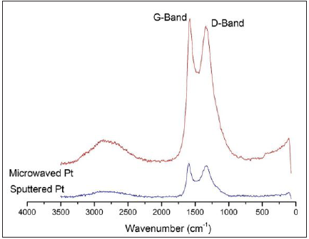
Raman spectroscopy characterization technique was employed to characterize the carbon skeleton structures in the two incubated samples differentiated by the different Pt-deposition methods. Both spectra obtained (Figure 9) display the D-band, a band around 1330cm-1 that is the result of a hybridized vibrational mode associated with the edges of graphene sheets, and G-band, a band around 1550-1580cm-1 arising from in-plane stretching of graphene sheets. The spectrum of the microwaved sample shows a peak ratio of the D-band to the G-band of about 1.7, while the same ratio of the sputtered sample is slightly greater (c.a. 1.9) than the above one. This implies that the sputtered sample has a higher quantity of edges of graphene than the microwaved sample [26]. This on the other hand proves the more delicate carbon spines that certainly contains a larger portion of edge of the stacked graphene sheets. In addition, the G band of the sputtered sample occurs at 1583cm-1, which is higher than the microwaved sample at 1556cm-1. This difference proposes that the graphene sheets of the later sample is relatively movable in-plane displacement, which may be interpreted as the result of containing more defects or a lower density of sheet stacking. Moreover, the presence of a broad band at 2750cm-1 is the 2nd-order “G” band, the overtone of the D-band frequency [27]. The relative peak intensity of this band relative to the respective G band is slightly stronger in the spectrum of the microwaved sample than in the sputtered sample, which coincides the above analysis about the difference in the G-band frequencies of these two samples.
Figure 9: Raman Spectra of the incubated samples initially prepared by the Pt-sputtering and (Sputtered Pt) and microwave depositing methods (Microwaved Pt).
Conclusion
This study demonstrates a finding of the growth of dendritic nanocarbon needles over the surface of an activated carbon flakes, which is pre-coated with a layer of platinum atom clusters, under a flow of N2-CO2 co-gas. This phenomenon has never been observed anywhere else before for a solid-gaseous interface nor ever for a solid carbon substance. The gas purge plays a vital role in this g-s reaction as it promps vortex field when meeting the hot carbon stream rising from carbon surface, but more importantly, the Pt atom clusters catalyze gasification of carbon (the reverse Boudouard reaction) by CO2 to produce CO. The instant disproportionation of CO provides carton atom stream for the in-situ growth of carbon dendrites. There are three conditions affecting this growth, firstly, the co-gas; secondly, the method to lay the Pt coating on carbon flakes; and thirdly, the polymer precursor to make the activated carbon flakes. The amount of platinum coating is also pivotal in the final structure of dendritic growth. Whilst treatment with lower concentrations of platinum colloids resulted in bushy tree-like structures, increasing the platinum atom cluster loading results in spikey cactus-like growth of carbon needle-like spines. As for the last factor, it requires the carbon flakes to be produced from a high oxygen-content polymer, e.g. hydroxyethyl cellulose or glucose polymer, but rather polypyrrole since the carbon flakes must be able to be gasified by CO2 under the catalysis of Pt atom clusters.
References
- Trivedi R, Kurz W (1994) Dendritic growth. International Materials Reviews 39(2): 49-74.
- Jan YN, Jan LY (2010) Branching out: Mechanisms of dendritic arborization. Nat Rev Neurosci 11(5): 316-328.
- Wong ROL, Ghosh A (2002) Activity-dependent regulation of dendritic growth and Nat Rev Neurosci 3(10): 803-812.
- Nacher J, Guirado R, Castillo GE (2013) Structural plasticity of interneurons in the adult brain: Role of PSA-NCAM and implications for psychiatric disorders. Neurochemical Research 38(6): 1122-1133.
- Shirao T, González-Billault C (2013) Actin filaments and microtubules in dendritic spines. Journal of Neurochemistry 126(2): 155-164.
- Miyata Y, Shima Y (1994) Self-consistent analytical theory of dendritic growth with Advanced Materials 93, Elsevier pp. 621-624.
- Haxhimali T, Karma A, Gonzales F, Rappaz M (2006) Orientation selection in dendritic evolution. Nat Mater 5(8): 660-664.
- Acer E, Erol H, Gündüz M (2013) Relationship between growth rates and dendritic microstructure parameters in Al-5wt. Zn binary alloy. Materials Science Forum 765: 215-219.
- Chen M, Hu XD, Ju DY, Zhao HY (2013) The microstructure prediction of magnesium alloy crystal growth in directional solidification. Computational Materials Science 79: 684- 690.
- Kaldre I, Fautrelle Y, Etay J, Bojarevics A, Buligins L (2013) Thermoelectric current and magnetic field interaction influence on the structure of directionally solidified Sn-10 wt.%Pb alloy. Journal of Alloys and Compounds 571: 50-55.
- Patakham U, Kajornchaiyakul J, Limmaneevichitr C (2013) Modification mechanism of eutectic silicon in Al-6Si-0.3Mg alloy with scandium. Journal of Alloys and Compounds 575: 273-284.
- Wu MW, Xiong SM (2012) Modeling of equiaxed and columnar dendritic growth of magnesium alloy. Transactions of Nonferrous Metals Society of China 22(9): 2212-2219.
- Zhao P, Vénere M, Heinrich JC, Poirier DR (2003) Modeling dendritic growth of a binary alloy. Journal of Computational Physics 188(2): 434-461.
- Criscione A, Kintea D, Tuković Z, Jakirlić S, Roisman IV, et al. (2013) Crystallization of supercooled water: A level-set-based modeling of the dendrite tip velocity. International Journal of Heat and Mass Transfer 66: 830-837.
- Akolkar R (2013) Mathematical model of the dendritic growth during lithium Journal of Power Sources 232: 23-28.
- Sun DK, Zhu MF, Pan SY, Yang CR, Raabe D (2011) Lattice Boltzmann modeling of dendritic growth in forced and natural convection. Computers & Mathematics with Applications 61(12): 3585-3592.
- Hunt JD, Lu SZ (1993) Numerical modelling of cellular and dendritic array growth: Spacing and structure predictions. Materials Science and Engineering: A 173(1-2): 79-83.
- Miyata Y, Shima Y (1994) Self-consistent analytical theory of dendritic growth with Advanced Materials 93, Elsevier pp. 621-624.
- Haxhimali T, Karma A, Gonzales F, Rappaz M (2006) Orientation selection in dendritic evolution. Nat Mater 5: 660-664.
- Zhou YE, Hong L (2013) The growth of porous carbon fibres through in-situ vapour RSC Advances 3: 19769-19773.
- Liu YY, Liu L, Hong L (2017) Gasification of char with CO2 to produce CO impact ofcatalyst carbon interface. Catalysis Today 281: 352-359.
- Sun M, Hong L (2011) Impacts of the pendant functional groups of cellulose precursor on the generation of pore structures of activated carbons. Carbon 49(7): 2173-2180.
- Liu Z, Lee JY, Chen W, Han M, Gan LM (2004) Physical and electrochemical characterizations of microwave-assisted polyol preparation of carbon-supported PtRu nanoparticles. Langmuir 20(1): 181-187.
- Kharissova OV, Kharisov BI (2010) Less-common nanostructures in the forms of Ind Eng Chem Res 49(22): 11142-11169.
- Lim YA, Babu P, Kumar R, Linga P (2013) Morphology of carbon dioxide-hydrogen-cyclopentane hydrates with or without sodium dodecyl sulfate. Cryst Growth Des 13(5): 2047-2059.
- Costa S, Borowiak PE, Kruszyñska M, Bachmatiuk A, Kaleńczuk RJ (2008) Characterization of carbon nanotubes by raman spectroscopy. Materials Science Poland 26(2): 433-441.
- Dresselhaus MS, Pimenta MA, Eklund PC, Dresselhaus G (2000) Raman scattering in fullerenes and related carbon-based materials, in: W Weber, R Merlin (Eds.) Raman Scattering in Materials Science, Springer Berlin Heidelberg pp. 314-364.
Publishers: https://crimsonpublishers.com/


it is a good article blog. thanks for sharing.
ReplyDeleteBlack nutritionist
Black dietitian
nyc eating disorder dietitian
haes nutritionist
registered dietitian nyc
African American dietitian
health at every size nutritionist