The Comparative Study of the Sway of Effect Pulse Energies of Pathways on AHSS-DP 350/600 and Simulation by Baidoo Philip in Determinations in Nanomedicine & Nanotechnology_Journal of Nanotechnology
Abstract
Fatigue crack growth test was executed to determine fatigue behavior in the metallic plates of AHSSDP350/ 600. However, this new material is widely used these days in medical instruments and automobile manufacturing industries, henceforth controlling fatigue character is a major challenge in the production unit. The influence of laser shock peening with multiple choice of pulse energies on AHSSDP350/ 600 was investigated comparatively with simulation. The research work done of LSP 3D hitches of industrialized of a 3D non-lined model of Finite Element Model (FEM) grounded in the ABAQUS/ Explicit software improvement of material properties was the ultimate objective. Measuring compared of both residual stress and fatigue cycle behavior comparatively to simulation was performed. It resulted that the compressive residual stress can be injected into the outer layer of the specimen, with LSP pulse energy of S20J, S30J, D20J, and D30J of experimental work done on the specimens correlated well with the simulation.
Keywords: Finite element model; AHSS-DP350/600; Laser shock peening; Simulation; Pulse energy; Residual stress
Introduction
Laser Shock Processing (LSP) is accountably novel material outward layer body modification technology. It employs high power laser to inflict a well-built hit wave on material outer body layer to refine the material structure and induce residual stress beneficially into outward appearance [1], worked on the effects of LSP on Nano-hardness, elastic modulus and surface residual stress of Fe-Ni alloy and investigated. The importance of tiny-hardness and elastic modulus on Fe-Ni alloy after LSP were measured by the Nano indentation technology. The marked residual effort outward layer by XRD with sin2ψ and Scanning Electron Microscopy (SEM) observation of the microstructure before and after LSP solutions were captured. Execute resulted that outer appearance of the tiny-hardness, elastic modulus and outward residual effort in LSP region, were obviously raised to a desirable point as against non-LSP region [2], emphatically alarmed on a paper the negative side of an absorbent overlay on the residual stress field using LSP setup and the energy level were evaluated. The Residual defects spread in multiples have a character of inner depth governed by the drilling behavior. It was seen that the overspread of residual stress move the writeabout to a position changed on the outer side on the specimen. The prevention of coating the specimen surface after LSP have improved wear and contact fatigue properties of this aluminum alloy [3]. Confirmed also in the work done on tiny-indentation used to handle measuring tiny films on mechanical properties, including elastic modulus and tiny-hardness. The pithy-hardness and elastic modulus samples manufacture have a series of effects by LSP during LY2 aluminum alloy worked. The outcome of the result shown Nano-indentation techniques values increased by 58.13% and 61.74% as compared to non-LSP. LPS improved metal mechanical strength which governed fatigue property and corrosion resistance were alarmed [4]. Investigated that the advance-cycle fatigue feats in accordance with 7085-T7651 aluminum treated with a sample of LSP and anodization. The Stress-feats and fatigue-data were ignited in a high-level humidity environment which used smooth (Kt=1) specimens test at a stress ratio (R=0.1). This resulted that shocked specimens chanced-out higher significant improvement in fatigue performance.
Comparatively traditional processed techniques can directly handle the treatment location and its deeper depth [5]. During their work on “Surface pre-stressing to step up fatigue strength of components by LSP”. It’s a competitive technique which provides multiple robust governed fatigue [6]. made this statement that to charmed fatigue improvement on structure material, LSP must use the effects of residual stress on fatigue behavior. The crack propagation of LSP worked hole marvelously good during this investigation. The changed location microstructure of 7050 aluminum at different intensities shown that LSP had an obvious inhibitory action to crack initiation and growth respect to fatigue. These investigations have verified that LSP attempted to minimize the condemned Fatigue Crack Paths (FCP). However, the researches focused on a comparative study on different pulse energy levels of AHSS-DP 350/600 peak outrage influence concernment on fatigue. In order to satisfied this requirement, a dog bone specimens non- LSP and LSP of different energies of 20J and 30J on a single-sided LSP impact and single double sides LSP impact named: (S20J; S30J; D20J; and D30J) and non-LSP impact were done on specimens before the following tests: hardness, roughness, residual stress, fatigue cycle, and microstructure morphologies.
This resulted clear and reported in [7], Philip Baidoo (2019) resulted that Residual stress analysis of LSP can be seen that the induced outward layer peak compressive residual stresses are increased by 3 times in D20J and 2 times in D30J when the LSP paths increased from 1 to 2 to 3 in both paths. It indicated that shocking pulse of square sharp edge introduced tiny cracks on the outward layer which the wave’s inner compressive residual stress vice versa with enclosure significantly stepped up with enlargement of LSP coverage area. The Quality of the specimen’s surface treatment of different energies of LSP was all improved. However, the highest fatigue cycle life before fractured among the specimens was D30J as compared to NOLSP respectively. It was significantly indicated that clearer differences of 16289 seconds before failure as compared to without LSP respectfully. The fatigue roughness of striation of the specimens of different energies with and without LSP revealed that the higher the energy levels the higher roughness and the lower the energy level the lower the smoothness of the surface of the specimens. From the AHSS-DP350/600 specimens with different energies, there was collectively changed of fatigue crack initiation outward layer and the fatigue striation spacing with LSP. However, it’s an alarming fact that the totality of all the experiments and its observations done on LSP specimens in this paper on AHSSDP350/ 600 had a great influence as compared to without LSP significantly. However, the researcher intended again to do research in the comparative study of the influence of impact pulse energies of LSP pathways on AHSS-DP 350/600 and numerical model (simulation).
Description of the numerical model
For the research work of LSP 3D hitches, therefore, the industrialized of a 3D non-lined model of Finite Element Model (FEM) grounded in the ABAQUS/Explicit software [8]. It deciphers the shock wave broadcast problematic into the solid substantial, through precise deliberation of its elastic-plastic comportments. From the opinion of interpretation of period alterations, the customary approach of unambiguous differencing for the preliminary reckless shock proliferation phase trailed by average unspoken differencing for the investigation of the concluding Compressive Residual Stress (CRS) symmetry is not hand-medown, in its place only clear differencing has stayed second-hand with long-time progresses in direction to scope stress equilibration. From the geometrical argument of understanding, a bursting 3D conformation for the factual geometry and for the successive touching approach double of throbs has been well-thought-out. The FEM elements castoff are eight-node bricks (namely C3D8R) with abridged incorporation and hourglass regulator in the preserved area and a six-node trilinear prism (namely C3D6) in the respite of the geometry, wherever there is no functional load, construction easier to mesh multifaceted geometries (Figure 1).
Figure 1: Optimized mesh.
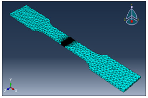
The element scope, in the preserved zone, permits upholding cunning junction and whose charge has remained intended by a directed merging examination through the model itself. An entire of 645,736 rudiments are rummage-sale in the complete network. As a consequence, the industrialized FEM model has the chief benefit of permitting the reproduction of LSP dispensation in actual geometries considering an enormous quantity of pulses terminated hefty zones, fetching a hike in superiority with deference to the maximum pertinent FEM models designated in literature, counting the following: Where Brockman et al. [9], industrialized a dependable investigation model to comprehend the multifaceted three-dimensional stress waves and envisage CRS [10], where Warren et al. simulated LSP seeing high pulse touching in a minor expanse where Faiedh HN et al. [11], developed a FEM model to calculate depression distortion produced by solitary LSP pulses and schoolwork the inspiration of proportion intersection and radioactivity approaches in CRS in an imperfect volume and where Ren et al. [12], simulated the thermal reduction of CRS in a simplified geometry.
Result and Discussion
FEM simulation
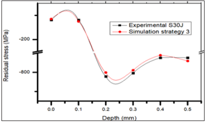
Simulations have shown that the residual stresses distribution in AHSS-DP 30/600 does not only depends on conventional LSP parameters and the induced residual stress dependency on the pulse sequence has been revealed specimens during fatigue testing of different energy levels of LSP. The strategy 1, 2 and 3 in Figure 2-4 are simulation parts of the experimental work of D20J, D30J and S30J specimens respectively. Its advancing direction of the treatment is parallel to the fatigue load. In order to perform the double-sided LSP, firstly the upper surface is peened and right after the bottom surface is peened. Figure 2-4 shows the simulation results after applied strategies. It can be seen that the induced residual stresses in the whole specimens, with views of both the upper and bottom surfaces and the cross-section respectively.
Figure 2: Residual stresses simulation results after strategy 1.
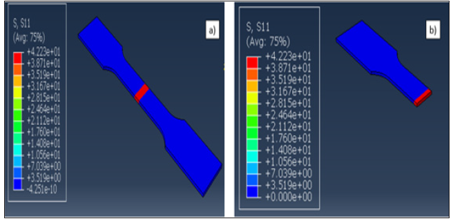
Figure 3: Residual stresses simulation results after strategy 2.
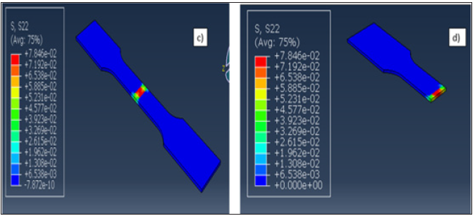
Figure 4: Residual stresses simulation results after strategy 3.
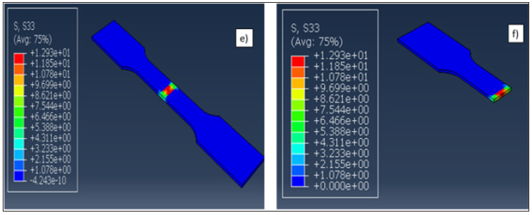
The residual stresses analysis indicates that the stress distribution presents a sandwich-type distribution in depths, with compressive stresses under the treated surfaces and tensile stresses between them (due to the self-equilibration stress in the material). From Figure 5-7, this induced tension in the mid-thickness could be problematic in case of its magnitude achieves moderate-high values, after strategy 1, 2 and 3 revealed. FEM results also show that the residual stress distribution is not exactly symmetric in depth, with noticeable differences between the residual stress magnitudes achieved in the surfaces, presenting more CRS in the upper surface than in the bottom surface. This difference is definitely related to the fact that both the upper surface and the bottom surface are not simultaneously peened (realistic experimental conditions are simulated). When LSP is applied to the bottom surface, the material has been pre-stressed already despite that the strategies 1, 2 and 3 are correlating well with the experiments.
Figure 5: Optimized mesh.
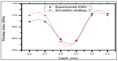
Figure 6: Optimized mesh.
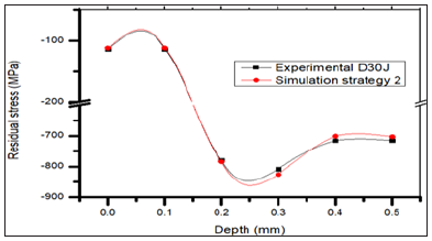
Figure 7: Optimized mesh.
Conclusion
Residual stress analysis of LSP can be seen that the induced outward layer peak compressive residual stresses are increased by 3 times in D20J and 2 times in D30J when the LSP paths increased from 1 to 2 to 3 in both paths. It indicated that shocking pulse of square sharp edge introduced tiny cracks on the outward layer which the wave’s inner compressive residual stress vice versa with enclosure significantly stepped up with enlargement of LSP coverage area. However, the simulation result correlated well to the experimental result.
References
- Cheng GG, Feng AX, Jiang YF, Lu JZ, Zhang L (2009) Effects of laser shock processing on mechanical properties of Fe-Ni alloy. Mater Des 30(9): 3673-3678.
- Banderas A, Gomez R, Molpeceres G, Ocaña C, Porro JL, et al. (2006) Effect of an absorbent overlay on the residual stress field induced by laser shock processing on aluminum samples. Appl Surf Sci 252(18): 6201-6205.
- Guan HB, Lu JZ, Luo KY, Qian XM, Zhang LF, et al. (2010) The microstructure mechanism for mechanical property of LY2 aluminum alloy after laser shock processing. Mater Des 31(5): 2599-2603.
- Hill MR, Luong H (2008) The effects of laser peening on high-cycle fatigue in 7085-T7651 aluminum alloy. Mater Sci Eng A 477(1-2): 208-216.
- Harris F, Hammersley G, Hackel LA (2000) Surface prestresing to improve fatigue strength of components by laser shot peening. Opt Lasers Eng 34(4-6): 327-337.
- Dai FZ, Ren XD, Ruan L, Sun GF, Yang HM, et al. (2013) The effects of residual stress on fatigue behavior and crack propagation from laser shock processing-worked hole. Mater Des 44: 149-154.
- Baidoo P (2019) The sway of effect pulse energies of pathways on AHSS-DP 350/600. Res Dev Material Sci 12(3).
- (2014) ABAQUS user’s manual. 6(13).
- Brockman R, Braisted W, Olson S, Tenaglia R, Clauer AH, et al. (2012) Prediction and characterization of residual stresses from laser shock peening. Int J Fatigue 36(1): 96-108.
- Warren AW, Guo YB, Chen SC (2008) Massive parallel laser shock peening: Simulation, analysis, and validation. Int J Fatigue 30(1): 188-197.
- Faiedh HN, Peyre P, Song H, Popa I, Ji V, et al. (2015) Finite element analysis of laser shock peening of 2050-T8 aluminum alloy. Int J Fatigue 70: 480-489.
- Ren XD, Zhang QB, Yuan SQ, Zhou JZ, Wang Y, et al. (2014) A finite element analysis of thermal relaxation of residual stress in laser shock processing NI based alloy GH4169. Mater Des J 54: 708-711.
https://crimsonpublishers.com/dnn/fulltext/DNN.000525.php


No comments:
Post a Comment