Crimson Publishers High Impact Journals

Monday, May 9, 2022

Applying High Salinity Water in Flotation-A Review_Crimson Publishers

Applying High Salinity Water in Flotation-A Review by Jinhong Zhang in  Aspects in Mining & Mineral Science_open access journals in Mining & Mineral Science


Abstract

The paper reviewed the application of high salinity water in flotation. The materials, of which flotation process high salinity water was use, were classified as four different categories, i.e., ions, soluble salt minerals, coal and sulfide. The mechanism of high salinity’s impact on flotation was also summarized.

Keywords: Mining; Salinity; Trace metals; Salt minerals; Flotation

Introduction

In mining industry, flotation consumes a large amount of fresh water, in spite of the fact that a portion of process water is recycled. Superficially it seems that there is no need to use fresh water for flotation because during flotation, water is mixed with rock which are “dirty”. This raises the logical question whether low quality water, such as river water, reclaimed water and high salinity water (sea water and groundwater), can be used for flotation with no decrease in the efficiency of the process. The present review will focus on the application of high salinity water in flotation. In general, the flotation process using high salinity water can be classified as the following different categories:

Flotation of trace heavy metal species in sea water

Some trace elements, for example, vanadium, selenium and indium and so on, are believed to play a role in the marine biosphere. However, the significance and involvement of these trace heavy elements is not clear yet. Starting from 1970’s, froth flotation began to be applied in analytical chemistry in the separation of a variety of trace ionic species in sea water to quantify these trace metals. The adsorption salt flotation technique was applied for the separation of vanadium and selenium from sea water [1,2]. Sonawane et al. [3] surveyed various surfactants for the flotation of iron (III), aluminum and indium hydroxide collector precipitates for concentrating trace heavy metals in sea water. It was recommended that a 1:3 mixture of sodium oleate and sodium dodecylsulfate gave stable foam-layer formation, which was believed to be essential to salt flotation and therefore a complete flotation. Cabezon et al. [4] used octadecyl amine as collector and Ferric hydroxide as co-precipitant to simultaneously separate copper, cadmium and cobalt from sea water by co-flotation.

Basically, specific cationic or anionic surfactant, called “collector”, was added into sea water and the collector will adsorb on the trace species and render the surface hydrophobic. The hydrophobized trace metal species will attach to bubbles in sea water and rise up forming foam layer for a further removal. Usually, anionic collector is chosen from sodium oleate and sodium alkyl sulfate; while cationic collector is alkyl amine. MIBC is a common frother. Because of the very high recoveries of the trace species based on spiked sea water samples, this pre-concentration by flotation has the advantages of being fast, simple and accurate over the classical techniques such as co-precipitation, co-crystallization and ion-exchange, which have been employed to pre-concentrate trace metals in sea waters.

Flotation of soluble salt minerals (potash, trona and borax) in saturated saline water

Potash is very important for the growth of plants and it is generally used as fertilizer in agriculture. Sylvite, the most important potash mineral, is abundant in saline lake deposits. The water soluble potash mineral has to be separated from other soluble salt mineral, such as halite and so on, before being further processed and made into fertilizer [5]. Historically, flotation process was first applied in 1940’s for the separation of two water soluble minerals, sylvite (KCl) and halite (NaCl), in their own saturated brine water and this event represented a milestone in the development of the flotation process. Now separation of watersoluble minerals by flotation is the most important present-day method of potash ore processing. In practice, both normal flotation and reverse flotation have been used for the separation of sylvite from halite [6]. Collector can be chosen from either cationic alkyl amine surfactant or anionic alkyl sulfate surfactant. Frother and conditioning agent are typically required for high flotation recovery and efficiency. Recently, a complete review work was published by Ozdemir et al. [7] showing that the ion specificity effect is the most important factor influencing salt flotation. In the specific work, the measurement such as solution viscosity, surface tension, bubbleparticle attachment time, contact angle, atomic force microscopy, sum frequency generation vibrational spectroscopy and molecular dynamics simulation have been used to study the air-solution and solid-solution interfacial phenomena.

Flotation of coal using sea water

The reason that sea water has been applied for coal flotation is mainly because in 1920 some coals were reported to be readily floated in sea water without the addition of reagents (collector and frother). In 1930’s, the flotation of coal using sea water was further investigated by Russian researchers [8]. The technique was later developed and called salt flotation, in which a high concentration of inorganic electrolyte is employed. Many studies have been carried out since then and it has been proposed that salt flotation is generally applied for naturally hydrophobic minerals, particularly for coal. Klassen and Vlasova [9] studied the flotation of coals of different rank in the presence of NaCl and reported that sea water can be a good self-frothing media in coal flotation. Results showed that high-rank coals can be successfully treated in NaCl solutions; however, flotation of the low-rank coals required the addition of hydrocarbons (petroleum). Fuerstenau et al. [10] studied the effect of surface functional groups on the salt flotation of coal and claimed that salt flotation was sensitive to coal functional group and it failed completely for heavily oxidized coal. They proposed that flotation rate increased substantially with increasing salt concentration, although the position of the maximum in floatability with respect to pH did not change. It was reported that increasing electrolyte concentration would introduce a more rapid thinning and rupturing of the film between particle and bubble. Yoon and Sabey [11] reported that salt flotation was better than conventional flotation by introducing faster flotation kinetics and a higher separation efficiency of removing ash from bituminous coal. Results showed that the frothability of salt solution increased with increasing salt concentration and divalent cations salts gave the best flotation results.

Li and Somasundaran [12-14] studied the effect of NaCl on coal flotation using a modified Hallimond tube and Zeta potential meter to delineate the role of the electrostatic interaction between bubbles and particles. It was reported that, at low salt concentrations and high salt concentrations, flotation exhibited showed different behavior. Botula et al. [15] studied the effect of saline water on coal flotation and reported that no statistically significant effect of water salinity (salt concentration or composition) was observed. Iskra et al. [16] investigated the effect of mine water salinity on flotation of coal slurries from Budryk Mine and reported that water salinity improves flotation kinetics and reduces reagents consumption. Hampton and Nguyen [17] studied the accumulation of dissolved gases at hydrophobic surfaces in water and NaCl solutions and discussed its implications for coal flotation in saline water in terms of attraction between hydrophobic surfaces in water, bubble/particle attachment and hydrophobic coagulation between particles. They reported that NaCl concentration (up to 1M) had a negligible influence on the geometry and population of pre-existing nanobubbles. Ozdemir et al. [18] focused on the surface chemistry aspects of coal flotation in bore water which was frequently used as process water in several flotation plants in Western Australia. Some surface chemistry techniques, such as bubble/particle attachment time experiment, zeta potential measurement, contact angle measurement and Atomic Force Microscopy (AFM) were applied to clarify the effect and mechanism of high salt/electrolyte concentrations.

Flotation of sulfide minerals using high salinity water

High salinity water has been applied for sulfide flotation generally in the arid areas such as Chile and Western Australia, where water is a precious commodity with little or no access sometimes. In practice, the concerns related to sulfide salt flotation are mainly focused on the impact of high salinity on flotation efficiency, the buildup of salt in recycled water and equipment corrosion. Sutulov [19] reported that successful flotation of copper minerals had taken place in Chile using sea water and the common buildup of dissolved mineral salts (Ca, Mg, Na) in recycled water was not a demonstrable problem. Vaughan and Dunne [20] studied the mineralogy and processing characteristics of Archean gold ores from Western Australia in highly saline ground water in the Yilgarn area. It was reported that the saline process water may interfere with processing in a variety of ways. For example, protective coatings were required because of the equipment corrosion problem in plants, arising from mainly the high NaCl content in groundwater. Wellham et al. [21] studied the role of carboxyl methyl cellulose in the flotation of a nickel sulfide transition ore. The hypersaline water used in the flotation plants was reported to make traditional serpentine dispersants ineffective.

Klimpel [22] claimed that sea water could be applied in flotation quite successfully. In addition, the hard water containing high levels of monovalent and divalent ions do not negatively affect the recovery and selectivity of water insoluble uncharged collectors with naturally floatable sulfide minerals. Rhodes and Penna [23] studied the flowsheet for the Sukari gold project, which is in one of the driest deserts in the world, in Egypt. The plant was designed to use sea water, which was pumped from the Red Sea 22km from the mine site, in the process plant grinding, leach and flotation circuits. Actually, a proportion of the water was treated in a reverse osmosis plant to produce fresh water for the gold circuit, mine services and power plant. Peng et al. [24] carried out a research on the flotation of a low grade pentlandite (nickel sulfide) ore containing large amounts of serpentine minerals from Mt. Keith in Western Australia using high salinity process water. Moreno et al. [25] reported the use of seawater as process water at Las Luces copper–molybdenum beneficiation plant in Taltal (Chile). In Las Luces plant, seawater is mixed with tailings pond water and used in the grinding and flotation circuits. It was claimed that the plant had successfully used seawater for many years without the use of any fresh water and a loss of water to evaporation could be a problem. In Chile, [26] which is located in the Atacama Desert, one of the driest desert in the world, at an elevation of 2100m above sea level became the first large-scale copper mine to only raw sea water in flotation.

Mechanism of High Salinity’s Impact on Flotation

The difference between high salinity water and fresh water is mainly because the ionic strength in the former is much higher. Many investigations have been carried out to study the impact of high ionic strength on coal flotation in inorganic electrolyte solutions and several theories have been proposed. Firstly, the inorganic electrolytes can prevent bubble coalescence which leads to reduced bubble size and increased population. These will further increase bubble-particle attachment efficiency and froth stability, hence flotation efficiency [11,27,28]. Secondly, it was proposed that high ionic strength may compress the electrical double layer (EDL) between bubbles and particles and therefore reduce the zeta potential of both bubbles and particles. The theory was supported by some experiment results showing that the flotation recovery achieved a maximum at a minimum zeta potential [10,11]. Thirdly, Klassen and Mokrousov [29] suggested that the inorganic electrolytes reduced the surface hydration of coal and destabilized the hydrated layers surrounding coal, which made the coal more hydrophobic and enhanced the bubble-particle attachment. However, this mechanism broke down in the case of naturally hydrophilic minerals, the flotation of which was not improved by the presence of high ionic strength.

Summary

The above review of using high salinity water in flotation shows that: 1) technically saline water can substitute for fresh water and be used in a large scale in flotation even without desalinization; 2) the impact of high salinity’s impact on flotation could be multifold. For some flotation systems, high salinity water increases flotation performance; while it does reversely in other cases; 3) the mechanism of high salinity’s impact on flotation depends on various conditions, such as ore type, ions species, ionic strength, pH, surface potential and others. As such, in practice, high salinity water may impact flotation in a complex way and it requires a systemic study for a specific case. An important prerequisite for this is that the chemistry of high salinity water will not evidently decrease flotation recovery and efficiency.

References

  1. Hagadone M, Zeitlin H (1976) The separation of vanadium from sea water by adsorption colloid flotation. Analytica Chimica Acta 86: 289-292.
  2. Tzeng JH, Zeitlin H (1978) The separation of selenium from sea water by adsorption colloid flotation. Analytica Chimica Acta 101(1): 71-77.
  3. Sonawane NJ, Hiraide M, Mizuike A (1983) Combined use of two surfactants for flotation of metal hydroxide precipitates in sea water. Analytica Chimica Acta 149: 359-362.
  4. Cabezon LM, Caballero M, Cela R, Perez JA (1984) Simultaneous separation of copper, cadmium and cobalt from seawater by flotation with amine and ferric hydroxide as collectors. Talanta 31(8): 597-602.
  5. DeVaney FD (1999) Flotation. Industrial and Engineering Chemistry 38(1).
  6. Titkov S, Panteleeva N, Chistyakov Pimkina AL, Mikhaylova I (2000) Studies of surface and sorption behavior of saline and clay carbonate minerals in electrolytes. Proceedings of the XXI International Mineral Processing Congress, Rome, Italy. pp. 23-27.
  7. Ozdemir O, Du H, Karakashev S, Nguyen A, Celik MS, et al. (2011) Understanding the role of ion interactions in soluble salt flotation with alkylammonium and alkylsulfate collectors. Advances in Colloid and Interface Science 163(1): 1-22.
  8. Luisenko PD (1935) Enrichment of the long-flame coals of LIS sitchansk by flotation with salts. Coke and Chem 5(10): 40-46.
  9. Klassen VI, Vlasova NS (1963) The effect of reagents in coal flotation. J of Mining Science 3(5): 504-510.
  10. Fuerstenau DW, Rosenbaum JM, Laskowski J (1983) Effect of surface functional groups on the flotation of coal. Colloid and Surfaces 8(2): 153-173.
  11. Yoon RH, Sabey JB (1989) Coal flotation in inorganic salt solution. In: Botsaris GD, Glazman YM (Eds.), Interfacial phenomena in Coal Technology. Marcel Dekker, New York. pp. 87-114.
  12. Li C, Somasundaran P (1991) Reversal of bubble charge in multivalent inorganic salt solutions-effect of magnesium. J Colloid Interface Sci 146(1): 215-218.
  13. Li C, Somasundaran P (1992) Effect of NaCl on coal flotation. SME Annual Meeting Phoenix, Arizona, USA. pp. 24-27.
  14. Li C, Somasundaran P (1993) Role of electrical double layer forces and hydrophobicity in coal flotation in sodium chloride solutions. Energy Fuels 7(2): 244-248.
  15. Botula J, Repka V (1996) Effect of saline water on flotation processing of coal. Uhli-Rudy-Geol Pruzkum 3(1): 13-14.
  16. Iskra J (1996) Effect of mine water salinity on flotation of coal slurries from the Budryk mine. Zesz Nauk Politech Slask Gom 231: 237-252.
  17. Hampton MA, Nguyen AV (2009) Accumulation of dissolved gases at hydrophobic surfaces in water and sodium chloride solutions: Implications for coal flotation. Minerals Engineering 22(9-10): 786-792.
  18. Ozdemir O, Taran E, Hampton MA, Karakashev SI, Nguyen AV (2009) Surface chemistry aspects of coal flotation in bore water. Int J Miner Process 92(3-4): 177-183.
  19. Sutulov A (1963) Flotation of minerals. Chile. pp. 124-126.
  20. Vaughan JP, Dunne RC (1987) Mineralogy and processing characters of Archen gold ores from Western Australia. Gold Mining, Australia. pp. 241-256.
  21. Wellham EJ, Elber I, Yan DS (1992) The role of carboxyl methyl cellulose in the flotation of a nickel sulphide transition ore. Miner Eng 5(3-5): 381-395.
  22. Klimpel R (1999) A review of sulfide mineral collector practice. In: Parekh BK, Miller JD (Eds.), Advances in Flotation Technology, USA.
  23. Rhodes M, Penna F (2009) Flowsheet development for the Sukari gold project in Egypt. World Gold Conference 2009. The Southern African Institute of Mining and Metallurgy, Australia. pp. 279-286.
  24. Peng Y, Seaman D (2011) The flotation of slime-fine fractions of Mt. Keith pentlandite ore in de-ionised and saline water. Minerals Engineering 24(5): 479-481.
  25. Moreno PA, Aral H, Cuevas J, Monardes A, Adaro M, et al. (2011) The use of seawater as process water at Las Luces copper-molybdenum beneficiation plant in Taltal (Chile). Minerals Engineering, Chile.
  26. Esperanza mine (2011) CESCO: Chile Antofagasta's Esperanza Gets Creative with Seawater.
  27. Yoon RH (1982) Flotation of coal using micro-bubbles and inorganic salts. Min Congr J 68(12): 76-80.
  28. Paulson O, Pugh RJ (1996) Flotation of inherently hydrophobic particles in aqueous solutions of inorganic electrolytes. Langmuir 12(20): 4808-4813.
  29. Klassen VI, Mokrousov VA (1963) An introduction to the theory of flotation. In: Leja J, Poling GW (Eds.), Butterworths, London.

For more articles in open access journals in Mining & Mineral Science
Please click on below link: https://crimsonpublishers.com/amms/

Friday, May 6, 2022

Prosthetically-Driven Alveolar Reconstruction: A Case Report_Crimson Publishers

Prosthetically-Driven Alveolar Reconstruction: A Case Report by Guaracilei Maciel Vidigal Junior in Modern Research in Dentistry_international journal of dentistry


Abstract

Prosthetically-driven alveolar reconstruction (PDAR) technique [1] is a method for alveolar ridge preservation/regeneration after tooth extraction without flaps, membranes or grafts with optimum aesthetic results. This case report presents a clinical situation where an upper right pre-molar exhibits an extensive buccal bone plate loss related to a late paraendodontic surgery failure. Using the PDAR technique complete bone regeneration was achieved using a minimally invasive procedure with optimum aesthetic results.

Keywords: Alveolar bone preservation/regeneration; Extraction socket; Coagulum; Fixed provisional prosthesis

Introduction

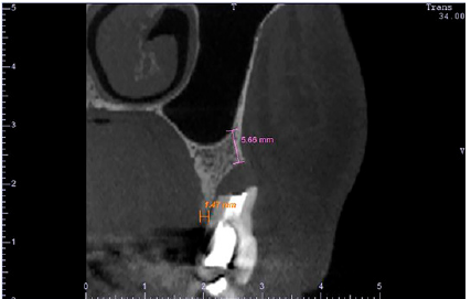
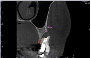
Prosthetically-driven alveolar reconstruction (PDAR) technique [1] is a method for alveolar ridge preservation/regeneration after tooth extraction and is indicated for extraction sockets with the absence of one bone wall (Figure 1) or even for an intact alveolus. It is based on alveolar occlusion, using a fixed provisional prosthesis with a specially designed pontic to provide stability to the coagulum and mechanical support to the gingival margin, preventing mucoperiosteal collapsing. There are some prerequisites when performing PDAR: teeth neighboring the compromised tooth area should be healthy and without proximal bone loss, and in esthetic areas, the gingival margin should be in harmony with the surrounding teeth and its contralateral counterpart. PDAR has a number of advantages, such as preservation of the preexisting alveolar bone by avoiding realizing incisions and flaps; regeneration of lost alveolar bone without the use of grafts or membrane barriers; and new bone formation in the space left by the tooth root using a minimally invasive procedure.

Case Presentation

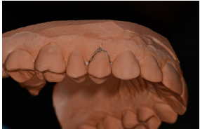
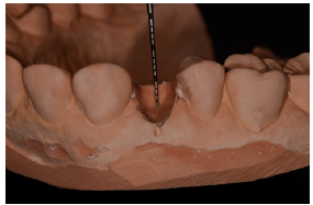
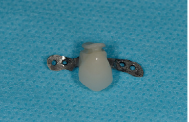
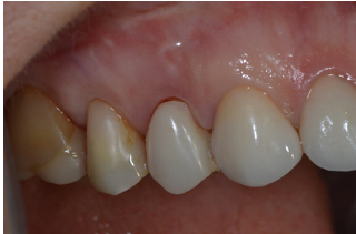
In this clinical case, the first upper right pre-molar presented recurrent abscess in the buccal aspect, associate to the failure of a paraendodontic surgery performed 6 years ago (Figure 2). To perform the PDAR technique, a provisional fixed prosthesis (which can be adhesive) was created using a working cast. The gingival margin of the tooth to be removed (Figure 3) was marked with a 0.5mm tip pencil. Then, the compromised tooth was removed from the cast and the “subgingival” area was excavated by approximately 3mm (Figure 4), preserving the gingival margins of the area previously marked in pencil, creating a cylindrical niche. The pontic was then created, completely filling the excavated subgingival area. Subsequently, a 1mm high and deep concavity was made in the intermediate subgingival millimeter, giving the subgingival area an hourglass shape (Figure 5). This concavity of the pontic is located subgingivally and will prevent gingival margin retraction. Ovoid pontics, by contrast, cause retraction of the gingival margin and failure of the procedure. The prosthesis disinfection should be performed by overnight immersion in 2% chlorhexidine solution.

Figure 1: CBCT cross-sectional image of the tooth showing the complete loss of the buccal bone wall. The initial buccal bone height was of 5.66mm (magenta) and the crestal bone thickness was of 1.47mm (orange).


Figure 2: The mucosa presented redness and edema caused by an endoperiodontal abscess.


Figure 3: On the working cast the gingival margins were marked with a 0.5mm tip pencil.


Figure 4: The tooth was removed, and a 3mm subgingival niche was excavated in the working cast.


Figure 5: The pontic completely fills the excavated subgingival area and have a 1mm high and deep concavity made in the intermediate subgingival millimeter.


Figure 6: 6-month clinical control.


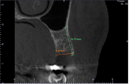
Figure 7: CBCT cross-sectional image shows a final buccal bone height of 14.74mm (green) and a crestal bone thickness of 9.16mm (orange) obtained without the use of grafts, membranes or flaps.


One hour before the surgery, the prosthesis should be immersed and kept in saline solution. It is extremely important that the whole subgingival area is rounded, with no sharp angles, well-polished and not over contoured, as this will cause recession of the mucosal margin, which may cause the procedure failure. Extraction was performed carefully using periotomes, without performing relaxing incisions and flaps. Before installation, the provisional prosthesis was tested to avoid direct contact with the bone, which can prevent its settlement into position. The provisional prosthesis was installed just after the tooth extraction using a fluid photopolymerizable resin (“Flow”). The patient was instructed not to floss in the pontic area. At the end of the healing period (Figure 6), after 6 months, a new cone beam computed tomography (CBCT) was performed to evaluate new bone formation (Figure 7).

Discussion

Traditional alveolar ridge regeneration techniques involve more invasive procedures with greater morbidity for patients (edema, pain, bruising). Traditional bone regeneration techniques may also involve other surgical sites, such as the donor area, or also higher costs for involving the use of biomaterials, such as grafts and membranes. Thus, PDAR is a less-invasive alternative, with no need for grafts or membranes, resulting in complete reconstruction of the alveolar ridge with optimum aesthetic results.

References

  1. Dantas LRF, Groisman M, Vidigal Jr GM (2013) Prosthetically-driven alveolar reconstructions - the next step. In: Complex situations on Implant Dentistry: specialized clinical solutions. Rossetti PHO, Bonachela WC (Eds.), VM Cultural Editora, São Paulo, Brazil, pp. 16-31.

For more articles in international journal of dentistry
Please click on below link: https://crimsonpublishers.com/mrd/

Thursday, May 5, 2022

Preventing Drug Addiction _Crimson publishers

Preventing Drug Addiction by Marvin Druger in Forensic Science & Addiction Research_Journal of Forensic Sciences


Opinion

I was a bit surprised when I received a request to write this article for the journal. After all, I don’t know much about forensics or addiction. I was a faculty member in biology and science education at Syracuse University for 47 years and I retired in 2009. I am now a professor emeritus. I am still involved in a number of activities at Syracuse University, including presenting a radio program on WAER-FM 88.3 (i.e., Science on the Radio); writing a regular column for 55 Plus magazine; organizing and directing two science programs for students; giving tours of the Syracuse University campus; and a variety of other activities. My proudest achievement is having taught more than an estimated 45,000 students.

In my entire life, I had only two episodes with marijuana. On one occasion, I was strolling near the tennis courts on the South Campus of Syracuse University. I spotted an isolated plant growing outside the tennis court. It looked like a marijuana plant. I plucked a leaf and brought it home and used my references to identify the plant. It was, indeed, a leaf from a marijuana plant. I didn’t know what to do with the leaf. Do I crush it and boil it, or roll it up and smoke it? I simply laughed and threw the leaf away.

On a second occasion, at a school reception, I came across a circle of graduate students. They were passing around a stubby cigarette and each student was taking a deep puff. I barged into the circle and said, “What’s that? The last Lucky Strike cigarette?” My wife grabbed my arm and escorted me away from the circle. “Come here,” she said, “I want to tell you something.” Of course, the stubby cigarette was marijuana.

I never, voluntarily, went anywhere near other more dangerous and powerful drugs. Moreover, I didn’t smoke. I once tried smoking a cigar. I took one puff, coughed and almost threw up. That was the end of cigars and smoking for me.

How about alcohol? I do have an occasional glass of wine or beer, but I really don’t like to have alcoholic drinks. When I’m at a social event, I don’t want to feel giddy and not know what I’m saying. I don’t need alcohol to stimulate my speech. I talk enough without that stimulus, and I like to have coherent conversations with people.

Although I didn’t acquire any of the usual addictions, I do have one major addiction, i.e., LIFE. I am addicted to doing as many positive things as I can, while I can. The theme that I would like to pass to readers is that” We learn from everything we do, and everything we do becomes part of who we are.” Nobody can escape this addiction to LIFE, although some people try to supplement or replace it with alcohol and drugs. I realize how difficult it must be to be “hooked” on drugs. The drug world becomes reality and the real world is by-passed. There is no simple solution to the problem of drug addiction. I believe that the best solution is not to get started with drugs in the first place. Easier said than done for many. Indeed, there are many reasons why drug addicts become drug addicts. In this article, I will not attempt to talk drug addicts out of their addiction. It’s impossible to cure addictions by simply trying to rationalize with a drug addict. Instead, I want to focus on positive thinking pathways to avoid getting addicted in the first place.

One way of avoiding addiction is to appreciate what life is really about and how special and sacred each life is. Every living thing is unique. Even identical twins, who have identical genotypes, are different. Each of us is the product of a genotype interacting with environments, and nobody can have the same environments. So, each of us has unique traits and each of us is special. This fact teaches us that someone can be taller, smarter, thinner, faster, etc. than someone else, but nobody is BETTER than anyone else. Each of us has unique, special traits and we should identify these traits and make the most of our positive ones. That’s what formal education should be all about, i.e., helping individuals to identify and nurture their unique talents and helping them discover where they fit in life.

Superimposed on the brevity and uniqueness of each individual life, is our place in the universe. The earth is located in one spiral arm of a galaxy called the Milky Way that contains more than 100 billion stars and their planets. The universe contains countless numbers of galaxies with stars and planets. Most scientists believe that there is life elsewhere in the universe, although distances may make it virtually impossible to communicate with or identify such life. It is mind-boggling to realize that each of us is a unique grain of sand on a vast beach with many other sand grains. So, in one sense, one grain of sand may seem unimportant because there are so many others on the beach. In another sense, each grain of sand is unique and that fact gives each grain significance. Just thinking deeply about the importance of a single life may influence someone to abstain from taking drugs and, instead, focus on making the most of unique abilities and life.

https://crimsonpublishers.com/fsar/fulltext/FSAR.000564.php


For more articles in Journal of Forensic Sciences
Please click on below link: https://crimsonpublishers.com/fsar/

Wednesday, May 4, 2022

Creative Light-Emitting Imaging on Textiles Integrated with Laser-Ablated Polymer Optical Fibres_Crimson Publishers

Creative Light-Emitting Imaging on Textiles Integrated with Laser-Ablated Polymer Optical Fibres by Frankie Ng in Trends in Textile Engineering & Fashion Technology_International journal of Textile Science & Engineering


Abstract

This paper reports the proposition and validation of the concept of innovative optical displays on textiles that used the RGB colour mode as well as surface-treated light-emitting fabrics integrated with the created polymer optical fibre (POF) materials. The POFs used were step-index optical fibres with a PMMA fibre core and a fluorinated PMMA derivative cladding. This type of structure exhibits suitable light transmission, thus overcoming the issue of leakage. The fabric structure was plain weave and the pattern of POF as the weft yarns was made of a set of three RGB colours used as a pixel unit. The colour was controlled by the RGB combination, and the light-emitting intensity was controlled by the number of notches produced through laser ablation on the POF. Weaving automatic loom machine and CO2laser machine were used to conduct experimentation and for subsequent creations. The successful creation of optical display on surface-treated light-emitting fabrics integrated with POF materials, a new design trend combined with POF materials on the basis of the RGB colour mode through laser micromachining technology resulted in innovative textiles. This in turn leads to the ultimate re-definition of art (fashion), humanities, and technology, which re-shape our culture and lifestyle and further enhance research in this area.

Keywords: Creative image display; Creative textiles; Polymer optical fibre; Laser micromachining

Background

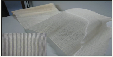
The past 40 years have seen the development of a new type of optical fibre, called POF [1]. This fibre is traditionally composed of a homogeneous core in polymethyl-methacrylate (PMMA) with a higher refractive index and cladded by fluorinated polymers with a lower refractive index. Until now, POFs have been developed, inter alia, for data communication and for networks in buildings, automobiles, railways, and aviation. These fibres have gradually started attracting attention in the textile industry because of their light weight, flat surface, and flexibility (Figure 1) [2]. These characteristics have made them easily connectable to light sources, such as light-emitting diodes (LEDs), thus rendering them suitable for large-area illumination [3] and adjustable in three-dimensional (3D) displays on wearable devices [4].

Figure 1: Photograph of woven fabrics produced from cotton yarns and POF of diameter 250μm [13].


This paper reports the study which aimed to explore, expand, and invent new weaving patterns using the RGB colour mode integrated into a fabric sheet. Every set of RGB colors (as weft yarns) serves as one pixel unit with cotton yarns as the wrap yarn. A broad array of colours can be reproduced and controlled by the RGB combination, and light-emitting intensity can be adjusted according to the number of notches created by CO2 laser ablation on the POF surface. The new designs emerge toward full colour optical displays on fabrics that cannot be otherwise manufactured using existing methods. The success of identifying, expanding, and inventing new weaving techniques with the new colour mode is of both original artistic merit and commercial value and will be a key design direction in this area. Consequently, the exciting creations from this project have attracted substantial interest in optical display fabrics for the public at large. Through this technology, fabrics integrated with POF using the RGB color mode will be significant in enhancing the design and technological values of textile and clothing merchandises in the increasingly competitive international fashion market.

POF to textile

Optical fiber connected with a light source was first developed more than 150 years ago by using glass [5]. With the development of plastic fibers in the 1960s, the concept of lighting fabrics by using POF in textile structures was published as a patent by DuPont in 1967 [6].

Today, processing of optical fibers in different textile technologies has led to various applications in displays, communication devices [3], and sensors, such as in medical, healthcare, architecture, public premises, stage, fashion design, and security and military devices. With connection to an external light source, POFs integrated in textiles allow light transmission not only to selected locations but also on the textile surface. For example, Kaschke [7] invented a light-emitting apparatus, called flexible flat panel displays 20 years ago. With the integration of light in textiles, many companies have caught up with the trend of combining modern design and functionality and have patented relevant up-to-date products. Remarkably, fibers or fiber-based systems have spurred numerous patents within the last century [8].

POF sensors are also well known [9]. Recently, scientists developed POFs as sensors for such applications as structural health monitoring [10] and strain and temperature detection [11].

Display technology with integration of POF in fabrics

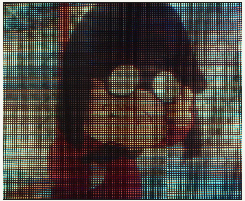
Perpendicularly oriented fibers of warp and weft can present images and information on flexible wearable substrates that exhibit information or designs on, for example, cars, portable electronic devices, and buildings, with the accelerated development of optoelectrical methods, especially LEDs (Figures 2a & 2b). Knocar [3] was the first one to produce flexible woven displays in cooperation with France telecom.

Figure 2a: LED display based on RGB matrix clusters.


Figure 2b: Close-up of a portion of the LED display based on RGB matrix clusters.


Optical fibers and LEDs are not only well established in the fields of optoelectronics and telecommunications, but also being applied in the textile industry to striking effect. Scientists have now learnt how to weave optical fibers and integrate them with textiles as well as manufacture flexible LED arrays and light-emitting fabrics [12]. The result is a new breed of visually striking photonic clothing that not only looks good but also has serious applications as ‘luminous fabrics devices’ (medical dressings for light therapy) [13] and garments with enhanced visibility and dynamic signage for pedestrians and cyclists [2].

Principle of light emission

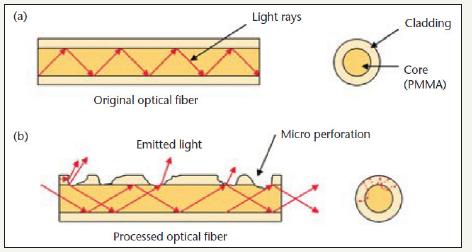
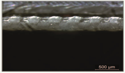
To acquire controlled pattern or colour, scientists have manufactured flexible LED displays and fabrics mainly using sideemitting POFs. The LED screen for fabric displays is composed of numerous surface units or pixels, each of which can be illuminated by light emitted from PMMA optical fibers with discrete index variation from one side of the fabric. The pixels are directly formed on optical fibers while transversely forming a spout of light on the fabric. This process generates micro-perforations, which reach the fiber core. The rest of the optical fiber, without any specific processing, transmits light on the surface while being invisible [3]. By using laser technology, certain features can be created in the core or at the core–cladding interface of the fiber; thus, the POF can emit light sideways, which offers possibilities for making exaggerated fashion statements and creating various design patterns [14] (Figures 3a & 3b).

Figure 3a: Laser ablated POF enabling light emission sideway.


Figure 3b: Laser ablated POF enabling light emission sideway.


Laser technology

Advances in laser technology have progressed so rapidly during the past decades that successful treatments have been developed and used for many aspects [15], such as laser micromachining technology on textile materials. Surface modification by chemical finishing methods is not environmentally friendly and can cause safety and pollution problems [16]. Consequently, laser technology applied as a physical treatment method is becoming widely adopted; it can be used in various applications to improve or even eliminate several problems of the traditional processes [17].

Designed patterns can be quickly and easily formed on POF surfaces by using laser [18]. A laser micromachining system with a computer graphic facility is a simple and controllable method for treating a large-sized POF [19]. CO2 infrared lasers are often used to ablate the underlying photo-thermal material. When the focused laser beam meets the material surface, the temperature of the irradiated spot increases so rapidly that the material melts, decomposes, and vaporizes, thus leaving a void in the work piece [20].

Laser ablation of polymers has been extensively investigated. For example, Srinivasan [21] discussed the relevance of photochemical and photo-thermal mechanisms in UV laser ablation. In addition, Cheng et al. [22] developed a flexible pipeline, improving the surface smoothness and easily introducing various functional groups on PMMA fabrics through laser micro machining.

PMMA micro fluidic systems are produced by a commercial CO2 laser system [23,24]. Surface properties, effects of laser power, and the processing speed of polymer materials irradiated by CO2 laser, including polyethylene terephthalate [25], polyethylene [26], polyester, and polyamide have also been investigated, which provides useful information on laser photo-thermal ablation on POFs exhibiting predetermined lights.

Despite the studies on laser micromachining technology and fabricated POF displays, surface-treated POFs with various patterns using the RGB colour mode integrated into a fabric sheet have not been investigated. Hence, several design possibilities can be explored for such POFs, and it is clear that the future development of optical display on fabrics in the fashion market will be a key research and design direction.

This study proposed to invent and adopt a completely new approach and method to realize a full-coloured light-emitting image creation on fabrics integrated with polymer optical fibre using laser micromachining technology which has not been conceived of and/or made possible before. The results of which were of high innovative application value and tremendous commercialization viability in terms of material and human resources. Successful outcomes of this project not only benefit application of the results in the fashion and textile industry, but also increased the competitiveness of nations which rely on the important role of their fashion and textile industry. The outcomes also further enhanced future research in this area.

Methodology

The initial phase of the proposed project was exploratory. A comprehensive review of the literature on POF fabrics and infrared laser micromachining technology was conducted to identify and expand the existing knowledge in these areas toward the creation of optical fabrics in the fashion market. Based on this accumulated information, the scope of the project was made increasingly specific and focused as the project progresses. Technologies and materials that are of high relevance and potential applicability to optical fabrics were selected and explored under controlled experimentation toward optimal visual and practical effects. Weaving automatic loom machine and CO2 laser machine were used to conduct experimentation and for subsequent creations. Further experiments were conducted with the V2000 versatile laser system.

Fabrics integrated with POF on the basis of RGB colour mode

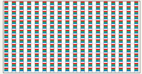
Figure 4a: Pattern of POF as the weft yarns and cotton as the warps proposed.


Figure 4b: The fabric with POF as the weft yarns and cotton as the warps produced.


The POFs used (ESKATM, CK-10, supplied by Mitsubishi Rayon Co., Ltd., Japan) were step-index optical fibers with a PMMA fiber core and a fluorinated PMMA derivative cladding. This type of structure exhibits suitable light transmission, thus overcoming the issue of leakage. The fiber diameter is 250μm and the numerical aperture is 0.5. The fibers were woven as the weft yarn with cotton yarns (32s/2, Central Textile, Hong Kong) as the wrap yarn by an automatic loom (the CCI Automatic Sample Loom SL7900). The fabric structure was plain weave (Figure 4a & 4b).

Direct-write laser machining treatment on lightemitting fabrics integrated with POF

A commercial CO2 laser system (Jeanologia Flexi-e V2) was used for laser micromachining. The pulsed CO2 laser has a wavelength of 10.6mm, and the duty cycle of the input power pulses is 50%. In this study, the beam width (spot size) is 0.2mm and the beam divergence of the laser is less than 2.0m rad. The output power density of the laser is 1.012W/cm2, which was measured using a laser power/energy meter (842-PE, Newport, USA). The cladding layer was removed by CO2 laser ablation, and the influencing factors, namely scanning speed and laser power density, were investigated.

Experiments on weaving structure

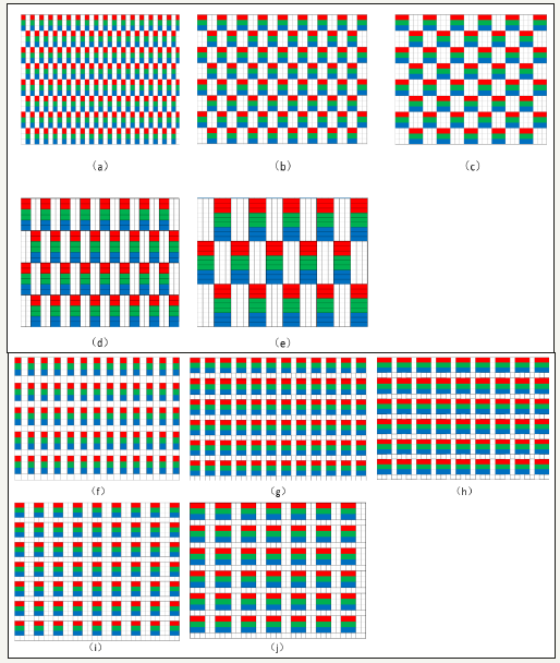
The initial weaving structures with each set of three fibers as a pixel unit were (a) 3/3 rib, (b) 3/2 matt weave, (c) 3/3 matt weave, (d) 6/6(2) matt weave, (e) 9/9(3) matt weave, (f) 3/1 plain+rib, (g) (3+1)2+1/3 matt weave, (h) 3/1(2=2) matt weave, (i) 3/1(3+1) matt weave, and (j) 3/1(3+2) matt weave (Figure 5a-5j). The final selected weaving structures for optical laser ablation effect were (a) 3/3 rib, (c) 3x3 matt weave, (f) 3/1 plain + rib, and (g) (3/1)2+1/3 matt weave.

Figure 5(a-j): Initial weaving structures with each set of three fibers as a pixel unit: (a) 3/3 rib, (b) 3/2 matt weave, (c) 3/3 matt weave, (d) 6/6(2) matt weave, (e) 9/9(3) matt weave, (f) 3/1 plain+rib, (g) (3+1)2+1/3 matt weave, (h) 3/1(2=2) matt weave, (i) 3/1(3+1) matt weave, (j) 3/1(3+2) matt weave.


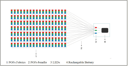
Groups of photonic fibers are bundled together and then connected with LEDs with predetermined sequences. By this way, the POF fabric can present a unique appearance with multiple and mixed colours (Figure 6).

Figure 6: Groups of photonic fibers bundled and connected with LEDs with predetermined sequences.


Experiments on laser micromachining POF

In this study, laser micromachining was deployed to remove part of the cladding of POF to allow light to emit on pre-designated spots along the surface of optical fibres. The fabric was placed on a platform, a laser beam was shoot on the surface of the fabric with POFs. The laser power was determined by two parameters: resolution (in dpi) and pixel time (in μs).

When POFs having treated with 20dpi and 130μs for 4 to 9 repeats, the engraving on POFs was acceptable. When the repeats were below 3 times, the engraving appeared insufficient. When the repeats were more than 10 times, the POF cores would break apart. When the POF was scanned by laser for 9 repeats, the ablation was not sufficient when treated with the parameters of 20 dpi and 120μs. It was found that 3 repeats were not sufficient when the POFs were treated with 20dpi and 140μs. Compared with 20dpi and 130μs, the engraved depth was similar when the POFs were treated with 5 to 7 repeats. However, when the repeats were up to 9 repeats, the POFs broke. When POFs were treated with 30dpi and 1 repeat, the laser ablated surface become rough and overlapping of ablated spots occurred. POFs have been severely burned and broken off when they were engraved with 30dpi and 120μs, 130μs and140μs in 1 repeat. It can be concluded that laser micromachining with 30dpi is not suitable for ablating the POFs used in this research. It was found that it was sufficient for POFs to treat with 2dpi and 140μs for 5 to 9 repeats. When POF was laser ablated with 20dpi and 130μs, the engraving was insufficient even if the POF was scanned by laser for 9 repeats. When it reached 10 repeats, emit light began to emit.

Results

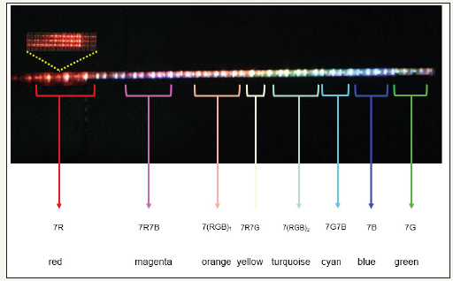
Based on the above finding with the images captured from the optical microscope, it can be concluded that a 250μm POF fabric to be engraved with a resolution of 20dpi, a pixel time of 130μs and 4 to 9 engraving repeats, and a 500μm POF fabric to be engraved with a resolution of 20dpi, 140μs pixel time and 5 to 9 repeats can achieve a satisfactory removal of POF cladding with no broken and overlapping for a satisfactory illuminating effect. The results enabled a fabric integrated with POFs to emit a colour spectrum from primary to tertiary shades of colours (Figure 7).

Figure 7: Light emitting POFs fabrics in rainbow gradation.


Acknowledgment

This research was funded by the Innovation and Technology Commission under the Innovation and Technology Fund of project and account numbers: ITS/149/16 - ZBP3.

References

  1. Zubia J, Arrue J (2001) Plastic optical fibers: An introduction to their technological processes and applications. Optical Fiber Technology 7(2): 101-140.
  2. Selm B, Gu¨ rel EA, Rothmaier M (2010) Polymeric optical fiber fabrics for illumination and sensorial applications in textiles. Journal of Intelligent Material Systems and Structures 21(11): 1061-1071.
  3. Koncar V (2005) Optical fiber fabric displays. Optics and Photonics News 16(4): 40-44.
  4. Shen J, Tao X, Ying D (2013b) Light-emitting fabrics integrated with structured polymer optical fibres treated with an infrared CO2 laser. Textile Research Journal 83(7): 730-739.
  5. Brochier C, Lysenko AA (2008) Optical fiber fabrics. Fibre Chemistry 40: 303-307.
  6. Derick BN, Synder JS (1967) Luminous textile products. Du Pont, USP Office, USA.
  7. Kaschke KD (1996) Optical fiber light emitting apparatus. Motorola, Inc, USP Office, USA.
  8. Dhawan A, Ghosh TK, Seyam A (2005) Fiber-based electrical and optical devices and systems. Textile Progress 36: 1-84.
  9. Bartlett RJ, Philip-Chandy R, Eldridge P, Merchant DF, Morgan R, et al. (2000) Plastic optical fibre sensors and devices. Transactions of the Institute of Measurement and Control 22: 431-457.
  10. Kuang KSC, Quek ST, Koh CG, Cantwell WJ, Scully PJ (2009) Plastic optical fibre sensors for structural health monitoring: A review of recent progress. Journal of Sensors 2009: 1-13.
  11. Peters K (2010) Polymer optical fiber sensors-a review. Smart Mater Struct 20(1): 1-17.
  12. Tao XM, Cheng XY, Yu JM (2008) Photonic fabric display with controlled pattern, colour, luminescence intensity, scattering intensity and light self-amplification. Patent 7466896, USA.
  13. Shen J, Chui CH, Tao XM (2013a) Luminous fabric devices for wearable low-level light therapy. Biomed Opt Express 4(12): 2925-2937.
  14. Graham-Rowe D (2007) Photonic fabrics take shape. Nature Photonics 1: 6-7.
  15. Tanzi EL, Lupton JR, Alster TS (2003) Lasers in dermatology: Four decades of progress. J Am Acad Dermatol 49(1): 1-34.
  16. Esterves F, Alonso H (2007a) Effect of CO2 laser radiation on surface properties of synethics fibres. Research Journal of Textile and Apparel 11(3): 42.
  17. Ortiz-Morales M, Poterasu M, Acosta-Ortiz SE, Compan I, Hernandex- Alvarado MR (2003) A comparison between characteristics of various laser-based denim fading processes. Optics and Lasers in Engineering 39(1): 15-34.
  18. Georgiou S, Kautek W, Kruger J (2004) Polymers and light. Springer, Berlin, Germany.
  19. Li B, Yu H, Sharon A (2004) Rapid three-dimensional manufacturing of micro fluidic structures using a scanning laser system. Appl Phys Lett 85: 2426-2428.
  20. Kawagoe M, Nakanishi M, Qui J (1997) Growth and healing of a surface crack in poly (methyl methacrylate) under case II diffusion of methanol. Polymer 38: 5969-5975.
  21. Srinivasan R (1993) Ablation of polymethyl methacrylate films by pulsed (ns) ultraviolet and infrared (9.17mm) lasers: a comparative study by ultrafast imaging. J Appl Phys 73: 2743-2750.
  22. Cheng JY, Wei CW, Hsu KH (2004) Direct-write laser micromachining and universal surface modification of PMMA for device development. Sens Actuators B 99(1): 186-196.
  23. Klank H, Kutter JP, Geschke O (2002) CO2-laser microma- chining and back-end processing for rapid production of PMMA-based micro fluidic systems. Lab Chip 2(4): 242-246.
  24. Snakenborg D, Klank H, Kutter JP (2004) Microstructure fabrication with a CO2 laser system. J Micromech Microeng 14(2): 82-89.
  25. Dadsetana M, Mirzadehb H, Shari N (1999) Effect of CO2 laser radiation on the surface properties of polyethylene terephthalate. Radiat Phys Chem 56(5-6): 597-604.
  26. Dadbin S (2002) Surface modification of LDPE film by CO2 pulsed laser irradiation. Eur Polym J 38(12): 2489-2495.

For more articles in International journal of Textile Science & Engineering
Please click on below link: https://crimsonpublishers.com/tteft/

Tuesday, May 3, 2022

Glucopuncture: Series of Regional Multiple Glucose 5% Injections_Crimson Publishers

Glucopuncture: Series of Regional Multiple Glucose 5% Injections by Jan Kersschot in Advances in Complementary & Alternative medicine_journal of traditional and complementary medicine


Definition

Glucopuncture is an injection-based therapy for the management of musculoskeletal conditions. It consists of multiple local injections with glucose or dextrose in low concentrations. These injections of G5W (Glucose 5% in Water) or D5W (Dextrose 5% in Water) seem to have a favorable effect on the repair mechanisms of damaged or inflamed tissues such as muscles, tendons, ligaments, cartilage, and peripheral nerves. The exact mechanism of action is not well understood and is likely multifactorial. Large randomized controlled trials are warranted to make specific recommendations regarding ideal protocols and indications. The introduction of a new term to describe these injections might give more exposure to its possible benefits among both patients and professional health care providers.

Keywords: Glucopuncture; Injection; Dextrose; Protocols; TRPV1 receptor; Scar tissue; Osteoarthritis; Glucose; Prolotherapy; Aerobic respiration; Cell metabolism; ATP-based theory; Primary sensory axons; Neurogenic inflammation; Chronic rotator

History

Glucose and dextrose injections have been used for decades in prolotherapy [1-26]. Prolotherapy - also known as proliferation therapy - is an injection technique which uses high concentrations of dextrose (more than 10% net concentration). Lidocaine is added to make the injections less painful. One of the aims of such hypertonic injections is to create an inflammatory reaction and / or stimulate formation of scar tissue in ligaments [27]. It is postulated that these dextrose injections stimulate tissue repair through growth factors and modulate pain modulation through agonism of TRPV1 receptor. As an increased matrix metalloproteinase (MMP) activity plays a major role in degradation of articular cartilage in patients with osteoarthritis, it is interesting to realize that glucose decreases IL-1β-induced MMP-1 expression in chondrocytes [28].

In prolotherapy, injections are given mainly into joint cavities, entheses, tendons and ligaments. It is suggested that prolotherapy can be as efficient as corticosteroid injections in the treatment of, for example, lateral epicondylosis [29,30], failed rotator cuff repair surgery [31] and chronic rotator cuff lesions [32]. It is also an interesting treatment modality in the treatment of osteoarthritis [33,34].

Over the last decade, low concentrations of dextrose 5% have become more popular [35-38]. These injections are administered into muscles, in the epidural liquid, near peripheral nerves [39], around tendons and in the skin. As the clinical effect is usually temporary, the sessions need to be repeated on a regular basis to achieve clinical effect. Although treatment protocols vary a lot, most physicians are using series of weekly injections of glucose 5% without adding local anesthetics in the treatment of osteoarthritis, carpal tunnel syndrome, back pain, sports injuries, whiplash, failed back surgery syndrome, regional pain syndrome and neuropathic pain.

The ATP Hypothesis

Glucose is a monosaccharide which functions as a precursor for many carbohydrates found in organisms. It is considered as the prime energy source for cellular health. One glucose molecule result in 38 ATP molecules during the aerobic respiration. The conversion of ATP into ADP releases 30.6kJ/mol energy to the cells. In other words, glucose can be considered as a provider of energy to the cell metabolism.

When tissues are damaged because of trauma, overuse or other causes, the cells need to regenerate as quickly as possible. This tissue regeneration requires an additional amount of energy. When energy supply is limited, complete recovery of the tissue may be slow or even impossible, leading to poor tissue healing. It is postulated that injecting glucose in the extracellular space of the damaged tissue may enhance ATP supply to the cells and as a result support and speed up local recovery. However, there is no strong evidence for this hypothesis so far. Only one study seems to support (partially) this ATP-based theory. In this recent study the authors have illustrated that injecting ATP in the spinal cord stimulates regeneration of primary sensory axons [40].

In the last decade, more findings about injections of low concentrations of glucose have been published. A prospective, randomized, double-blind, controlled trial illustrated a six-month efficacy of perineural dextrose for carpal tunnel syndrome [41]. Dextrose 5% injections also seem to be beneficial for patients with chronic low back pain (failed back surgery syndrome) [42]. Epidural injection of 5% dextrose is reported to reduce pain temporary, but a waning pain control at 2 weeks suggests the need to assess the effect of serial dextrose epidural injections [43]. Caudal epidural injection of 10mL of D5W (without anesthetic) every 2 weeks for 4 treatments and then as needed for 1 year resulted in a consistent pattern of post injection analgesia [44]. This suggests a potential sensorineural effect of serial dextrose injections on neurogenic pain, probably by targeting the peptidergic nociceptors. One proposed mechanism of action suggests that dextrose binds to presynaptic calcium channels and inhibits the release of substance P and CGRP, thereby decreasing neurogenic inflammation [37].

These observations generate the idea that glucose 5% injections (without anesthetic) might be an inexpensive and safe option in the treatment of sports injuries, carpal tunnel syndrome, musculoskeletal pain, whiplash, regional pain syndrome and osteoarthritis. In contrast to cortisone, longer series of such injections every week or every two weeks have little or no side effects. The downside of Glucopuncture is that more sessions are needed to attain symptom resolution when compared to cortisone injections or to PRP injections [45,46], although one study showed that intraarticular glucose injections in the sacroiliac joint produced longer lasting effects than those of steroid injections [47]. In other words, steroid injections provide probably better results on the short run while glucose injections may be superior when it comes to long term results.

Clinical Application of Glucopuncture

Glucose in a five percent water solution (G5W) is a sterile liquid which can be injected without adding a local anesthetic. Adverse reactions are not well documented but appear to be extremely rare (e.g., itching, allergic dermatitis). Temporary injection site tenderness and bruising are the most frequently reported side effects. Injections are given intracutaneously, subcutaneously, in joints and into muscles. Glucose 5% can also be injected around tendons, ligaments, and peripheral nerves. Usually multiple injections (5 to 10 injections) are given in the zone of tissue repair or in the pain zone (the zone which the patient points out as the painful area). Needles frequently used are 30G (1/2”), 27G (3/4” or 1 1/2”) and 23G (3”). The total volume injected varies from 5 to 15ml in each treatment zone. In acute cases, injections are given once or twice a week, and one to five sessions might be necessary. In chronic cases, five to ten sessions (first once a week and then every two weeks) might be needed to attain tissue repair and / or lasting pain relief.

When glucose (or dextrose) is injected in normal healthy tissue, the influence on cell metabolism is minimal. But it is hypothesized that when glucose is injected in tissues which lack energy supply, the added extracellular glucose may lead to more ATP production in the cell and thus support the natural repair processes in those damaged cells. When injected into a muscle tear, the muscle fibers seem to heal quicker and better [48]. As a result, it seems an interesting option to use injections of G5W in trigger points for the treatment of myofascial pain. Glucose injections are also applied in peripheral nerves. Especially chronic inflamed nerves seem to react well to Glucopuncture. Even the peripheral nerve endings in the skin and under the skin recover quicker from neural inflammation when injected with glucose 5%. More clinical research might illustrate the hypothesis that chronic regional pain syndrome [49] might be treated successfully and safely with subcutaneous (SC) or intracutaneous (IC) glucose injections.

Conclusion

Glucopuncture is a new term to describe regional multiple injections with glucose 5%. It is hypothesized that a series of sessions of multiple injections of glucose 5% supports the repair of damaged tissue such as muscles, tendons, ligaments, cartilage, and peripheral nerves. This injection technique can be applied as a single or as an adjuvant modality in the treatment of sports injuries, posttraumatic pain, osteoarthritis, neuropathic pain, and myofascial pain. More clinical and fundamental research in this area is necessary to verify the mechanism of action, safety, and long-term results of this technique.

References

  1. Reeves KD, Sit RW, Rabago DP (2016) Dextrose prolotherapy: a narrative review of basic science, clinical research, and best treatment recommendations. Phys Med Rehabil Clin N Am 27(4): 783-823.
  2. Distel LM, Best TM (2011) Prolotherapy: a clinical review of its role in treating chronic musculoskeletal pain. PM R 3(6 Suppl 1): S78-81.
  3. Ganji R (2018) Dextrose prolotherapy for improvement of rotator cuff lesions: ready for clinical use? Hong Kong Med J 24(4): 429-430.
  4. Hauser RA, Lackner JB, Steilen MD, Harris DK (2016) A systematic review of dextrose prolotherapy for chronic musculoskeletal pain. Clin Med Insights Arthritis Musculoskelet Disord 9: 139-159.
  5. Topol GA, Podesta LA, Reeves KD, Marcia MG, Lanny LJ, et al. (2016) Chondrogenic effect of intra-articular hypertonic dextrose (prolotherapy) in severe knee osteoarthritis. PM R 8(11): 1072-1082.
  6. Rabago D, Kijowski R, Woods M, Patterson JJ, Mundt M, et al. (2013) Association between disease-specific quality of life and magnetic resonance imaging outcomes in a clinical trial of prolotherapy for knee osteoarthritis. Arch Phys Med Rehabil 94(11): 2075-2082.
  7. Rabago D, Nourani B (2017) Prolotherapy for osteoarthritis and tendinopathy: a descriptive review. Curr Rheumatol Rep 19(6): 34.
  8. Rabago D, Kansariwala I, Marshall D, Nourani B, Stiffler JM, et al. (2019) Dextrose prolotherapy for symptomatic knee osteoarthritis: feasibility, acceptability, and patient-oriented outcomes in a pilot-level quality improvement project. J Altern Complement Med 25(4): 406-412.
  9. Kim BK, Shin JY, Seo KM (2001) The effect of prolotherapy for the chronic pain of musculoskeletal system. The Journal of the Korean Academy of Rehabilitation Medicine 25: 128-133.
  10. Kim MY, Na YM, Moon JH (1997) Comparison on treatment effects of dextrose water, saline, and lidocaine, and saline for trigger point injections. J Korean Acad Rehabil Med 21: 967-973.
  11. Chou Y, Chiou HJ, Wang HK, Lai YC (2020) Ultrasound-guided dextrose injection treatment for chronic myofascial pain syndrome: a retrospective case series. J Chin Med Assoc 83(9): 876-879.
  12. Lin CL, Huang CC, Huang SW (2019) Effects of hypertonic dextrose injection in chronic supraspinatus tendinopathy of the shoulder: a randomized placebo-controlled trial. Eur J Phys Rehabil Med 55(4): 480-487.
  13. Lee DH, Kwack KS, Rah UW, Yoon SH (2015) Prolotherapy for refractory rotator cuff disease: retrospective case-control study of 1-year follow-up. Arch Phys Med Rehabil 96(11): 2027-2032.
  14. Louw WF, Reeves KD, Lam SKH, Cheng AL, Rabago D (2019) Treatment of temporomandibular dysfunction with hypertonic dextrose injection (prolotherapy): a randomized controlled trial with long-term partial crossover. Mayo Clin Proc 94(5): 820-832.
  15. Arias VPI, Tovilla ZCA, Legorreta RBG, Wajid BF, Dory MR, et al. (2019) Prolotherapy for knee osteoarthritis using hypertonic dextrose vs other interventional treatments: systematic review of clinical trials. Adv Rheumatol 59(1): 39.
  16. Catapano M, Zhang K, Mittal N, Sangha H, Onishi K, et al. (2020) Effectiveness of dextrose prolotherapy for rotator cuff tendinopathy: a systematic review. PM R 12(3): 288-300.
  17. Hsieh PC, Chiou HJ, Wang HK, Lai YC, Lin YH (2019) Ultrasound-guided prolotherapy for acromial enthesopathy and acromioclavicular joint arthropathy: a single-arm prospective study. J Ultrasound Med 38(3): 605-612.
  18. Bayat M, Raeissadat SA, Mortazavian BM, Rahimi DS (2019) Is dextrose prolotherapy superior to corticosteroid injection in patients with chronic lateral epicondylitis? a randomized clinical trial. Orthop Res Rev 11: 167-175.
  19. Bertrand H, Reeves KD, Bennett CJ, Bicknell S, Cheng AL (2016) Dextrose prolotherapy versus control injections in painful rotator cuff tendinopathy. Arch Phys Med Rehabil 97(1):17-25.
  20. Hooper RA, Ding M (2004) Retrospective case series on patients with chronic spinal pain treated with dextrose prolotherapy. J Altern Complement Med 10(4): 670-674.
  21. Fullerton BD (2018) Prolotherapy for the thoracolumbar myofascial system. Phys Med Rehabil Clin N Am 29(1): 125-138.
  22. Ongley MJ, Inklebarger J (2020) The diagnosis and management of upper gluteal pain. Journal of Prolotherapy 12: e1009-e1014.
  23. Sit RW, Chung VCh, Reeves KD, David R, Keith KC et al. (2017) Hypertonic dextrose injections (prolotherapy) in the treatment of symptomatic knee osteoarthritis: A systematic review and meta-analysis. Sci Rep 6: 25247.
  24. Nagori SA, Jose A, Gopalakrishnan V, Roy ID, Chattopadhyay PK, et al. (2018) The efficacy of dextrose prolotherapy over placebo for temporomandibular joint hypermobility: A systematic review and meta-analysis. J Oral Rehabil 45(12): 998-1006.
  25. Rhatomy S, Evlin M, Rizki R (2020) Dextrose prolotherapy for muscle, tendon and ligament injury or pathology: a systematic review. Annual Research & Review in Biology 2020: 43-62.
  26. Ozkan O, Torgutalp SS, Karacoban L, Donmez G, Korkusuz F (2020) Do pain and function improve after dextrose prolotherapy or autologous platelet-rich plasma injection in longstanding groin pain? Monten J Sports Sci Med 9(2): 5-12.
  27. Hackett GS, Hemwall GA, Montgomery GA (1993) Ligament and tendon relaxation treated by prolotherapy. Oak Park, USA
  28. Wu TJ, Lin CY, Tsai CH, Huang YL, Tang CH (2018) Glucose suppresses il-1β-induced mmp-1 expression through the fak, mek, erk, and ap-1 signaling pathways. Environ Toxicol 33(10):1061-1068.
  29. Carayannopoulos A, Borg SJ, Sokolof J, Meleger A, Rosenberg D (2011) Prolotherapy versus corticosteroid injections for the treatment of lateral epicondylosis: a randomized controlled trial. PM R 3(8): 706-715.
  30. Yelland M, Rabago D, Ryan M, Shu KN, Dinusha V, et al. (2019) Prolotherapy injections and physiotherapy used singly and in combination for lateral epicondylalgia: a single-blinded randomized clinical trial. BMC Musculoskelet Disord 20(1): 509.
  31. Akpancar S, Örsçelik A, Seven MM, Koca K (2019) The effectiveness of prolotherapy on failed rotator cuff repair surgery. Turk J Phys Med Rehabil 65(4): 394-401.
  32. Seven MM, Ersen O, Akpancar S, Ozkan H, Turkkan S, et al. (2017) Effectiveness of prolotherapy in the treatment of chronic rotator cuff lesions. Orthop Traumatol Surg Res 103(3): 427-433.
  33. Works, Cynthia MD; Miller, Jesse DO (2020) Is prolotherapy effective in reducing pain and improving function in patients with knee OA? Evidence-Based Practice: 23(3): 19-20.
  34. Gül D, Orsçelik A, Akpancar S (2020) Treatment of osteoarthritis secondary to developmental dysplasia of the hip with prolotherapy injection versus a supervised progressive exercise control. Med Sci Monit 26: e919166.
  35. Köroğlu Ö, Orscelik A, Karasimav Ö, Demir Y, Solmaz İ (2019) Is 5% dextrose prolotherapy effective for radicular low back pain? Gulhane Medical Journal 61(3): 123-127.
  36. Lyftogt J (2007) Subcutaneous prolotherapy for achilles tendinopathy: the best solution? Australasian Musculoskeletal Medicine p. 107-109.
  37. Weglein AD (2001) Neural prolotherapy. Journal of Prolotherapy 3(2): 639-643.
  38. Paprottka KJ, Lehner A, Fendler WP, Harun I, Axel R, et al. (2016) Reduced periprocedural analgesia after replacement of water for injection with glucose 5% solution as the infusion medium for 90y-resin microspheres. J Nucl Med 57(11): 1679-1684.
  39. Chen SR, Shen YP, Ho TY, Chen LC, Wu YT (2018) Ultrasound-guided perineural injection with dextrose for treatment of radial nerve palsy: A case report. Medicine (Baltimore) 97(23): e10978.
  40. Wu D, Lee S, Luo J, Xia H, Gushchina S, et al. (2018) Intraneural injection of atp stimulates regeneration of primary sensory axons in the spinal cord. J Neurosci 38(6): 1351-1365.
  41. Wu YT, Ho TY, Chou YC, Ming JK, Tsung YL, et al. (2017) Six-month efficacy of perineural dextrose for carpal tunnel syndrome: a prospective, randomized, double-blind, controlled trial. Mayo Clin Proc 92(8): 1179-1189.
  42. Solmaz İ, Akpancar S, Örsçelik A, Yener KÖ, Gül D (2019) Dextrose 5% injections for failed back surgery syndrome: a consecutive case series. Eur Spine J 28(7): 1610-1617.
  43. Maniquis SL, Dean RK, Jeffrey RH, Lyftogt J, Cassie GC, et al. (2016) Short term analgesic effects of 5% dextrose epidural injections for chronic low back pain: a randomized controlled trial. Anesth Pain Med 7(1): e42550.
  44. Maniquis SL, Reeves KD, Rosen HJ, John L, Cassie GC, et al. (2018) Analgesic effect and potential cumulative benefit from caudal epidural d5w in consecutive participants with chronic low-back and buttock/leg pain. J Altern Complement Med 24(12): 1189-1196.
  45. Wu YT, Ke MJ, Ho TY, Li TY, Shen YP, et al. (2018) Randomized double-blinded clinical trial of 5% dextrose versus triamcinolone injection for carpal tunnel syndrome patients. Ann Neurol 84(4): 601-610.
  46. Shen YP, Li TY, Chou YC, Tsung YH, Ming JK, et al. (2019) Comparison of perineural platelet-rich plasma and dextrose injections for moderate carpal tunnel syndrome: A prospective randomized, single-blind, head-to-head comparative trial. J Tissue Eng Regen Med 13(11): 2009-2017.
  47. Kim WM, Lee HG, Jeong CW, Kim CM, Yoon MH (2010) A randomized controlled trial of intra-articular prolotherapy versus steroid injection for sacroiliac joint pain. J Altern Complement Med (12): 1285-1290.
  48. Tsai SW, Hsu YJ, Lee MC, Huang HE, Huang CC, et al. (2018) Effects of dextrose prolotherapy on contusion-induced muscle injuries in mice. Int J Med Sci 15(11): 1251-1259.
  49. Thor JA, Mohamed HNH, Halil H, Suhaimi A (2017) Perineural injection therapy in the management of complex regional pain syndrome: a sweet solution to pain. Pain Med 18(10): 2041-2045.

For more articles in journal of traditional and complementary medicine
Please click on below link: https://crimsonpublishers.com/acam/

Monday, May 2, 2022

Phytopathogenic Fungi: Useful Tools to Degrade Plant Biomass for Bioethanol Production_Crimson Publishers

Phytopathogenic Fungi: Useful Tools to Degrade Plant Biomass for Bioethanol Production by Gabriela Piccolo Maitan Alfenas in Modern Concepts & Developments in Agronomy_journal of agronomy and crop science


Abstract

Phytopathogenic fungi are able to produce enzymes for cell wall degradation when they attack the hosts and there is a close relationship between the capacity of enzymatic secretion and the virulence of these microorganisms. These enzymes are promising for biotechnological purposes and plant biomasses play an important role for induction of their production by fungal species. Biomass is an economic alternative to reduce pollution and to produce renewable fuels. The fungal enzymes are mainly applied for the hydrolysis step of bioethanol production process, which is environmentally friend. Many phytopathogen fungi are considered promising for enzymes production such as Chrysoporthe cubensis, Ceratocystisfimbriata and Fusarium verticillioides.

Introduction

Plant biomasses

Residues from agriculture, forests and industries have highly increased with the expansion of the world population and studies stipulate that there will be around 8.5 billion of persons by 2030 in the planet, which could cause serious environmental and socioeconomic consequences [1]. However, agricultural by-products, which are lignocellulosic wastes, constitute promising renewable resources for bioethanol production since they are widely available and rich in polysaccharides as cellulose and hemicellulose [2]. The use of plant biomasses as renewable energy reduces environmental problems such as pollution and fires [1]. For bioethanol production from plant biomass, three major steps are necessary: pretreatment, hydrolysis and fermentation. Pretreatment is required to alter the biomass structure and to facilitate the enzymatic access; enzymatic hydrolysis converts polysaccharides into monomeric sugars; and fermentation turns these sugars into ethanol [3]. The enzymatic hydrolysis is the major bottleneck of the process due to the reduced efficiency and the high costs of enzymes and fungi are the main producers of the enzymes for this step [3].

Phytopathogen fungi

Due to the expansion of planted areas, selection of most productive genotypes, climate changes and transit of people and products, the occurrence of biotic diseases, especially caused by fungi has increased, leading to great damages on crop yields [4]. Nearly 10 % of the identified fungal species can cause disease in more than 10,000 plants and they show different mode of actions since some fungi invade and colonize all tissues while others attack specific parts of the plants such as seeds, leaves, roots or stems [5]. Therefore, several alternatives are employed to control fungal diseases on plants, from the use of synthetic fungicides to the application of biological controls [6]. However, to cause a disease, phytopathogen fungi secrete enzymes to degrade hosts cell walls and there is a close relationship between the capacity of enzymatic secretion and the fungal pathogenicity [7]. The production of extracellular enzymes occurs not only to digest the polymers and to obtain nutrients for survival but also to degrade the cell wall barrier for penetration and spread through the plant tissue [8]. Thus, a more virulent phytopathogen shows great appeal for enzymes production.

Worldwide interest has focused on producing enzymes from phytopathogenic fungi for several biotechnological applications, including degradation of plant biomasses, i.e. agricultural residues, for bioethanol production. Sugarcane bagasse, rice husk, soybean hulls, powder toothpick yerba mate, corn and sorghum stover and wheat bran are some of the most used biomasses for enzymatic production by fungi [7,9,10]. The produced enzymes are mainly applied for bioethanol production, which between the alternative energy sources, is efficient and considered environmentally friend due to its sustainable properties [1]. It is worthy to mention that plant biomasses are used to cultivate fungi and to induce their enzymatic production, but also as substrates for bioethanol production, since they can be hydrolyzed into fermented sugars.

Enzymes from phytopathogenic fungi

Many phytopathogen fungi are promising for enzymes production applied in the hydrolysis step for bioethanol production processes. Recently, our research group has published data about Chrysoporthe cubensis (Bruner) Gryzenhout & Wingf MJ [11], Ceratocystis fimbriata Ellis & Halst and Fusarium verticillioides (Sacc.) Nirenberg. Chrysoporthe cubensis causes Chrysoporthe canker, one of the most important diseases of Eucalyptus spp. in tropical and subtropical areas of the world [10]. This fungus releases lignocellulolytic enzymes as cellulases, hemicellulases, laccases and accessory enzymes of interest capable of efficiently catalyze the hydrolysis of plant biomasses such as sugarcane bagasse [7,9,12-14]. Ceratocystis fimbriata was firstly described by Halsted in 1980, causing sweet potato rot, and it is largely found in several environments, mainly attacking crops in tropical climate areas [15]. This fungus is able to produce an accessory enzyme, β-xylosidase, essential for hemicellulose hydrolysis of sugarcane bagasse [16]. Fusarium verticillioides cause disease on maize plantations representing a serious economic threat to its production and quality [17]. This fungus is able to secrete endoglucanase, the first enzyme to act on cellulose, and a multienzymatic complex that contains two endoglucanases, one cellobiohydrolase and one xylanase for biomass degradation [18].

Final considerations

Although we recognize the negative impact of the phytopatogenic fungi on crop yields, concerning the serious consequences of the distinct diseases, it is important to emphasize that these microorganisms are useful for biotechnological purposes, especially production of enzymes for agricultural residues degradation. These enzymes are normally induced by biomasses, which is promising for the environment and the economy, since the lignocellulosic residues are highly available non-expensive resources. Applying enzymes from phytopatogenic fungi for generation of renewable fuels is a great possibility to regenerate waste and to extract useful metabolites from these microorganisms.

References

  1. Rodrigues A, Latawiec A (2018) Rethinking organic residues: the potential of biomass in Brazil. Modern Concepts & Developments in Agronomy 1(4): 73-77.
  2. Astolfi V, Astolfi AL, Mazutti MA, Rigo E, Di Luccio M, et al. (2019) Cellulolytic enzyme production from agricultural residues for biofuel purpose on circular economy approach. Bioprocess Biosyst Eng 42(5): 677-685.
  3. Maitan Alfenas GP, Visser EM, Guimarães VM (2015) Enzymatic hydrolysis of lignocellulosic biomass: converting food waste in valuable products. Current Opinion in Food Science 1: 44-49.
  4. Seidl R, Thom D, Kautz M, Martin Benito D, Peltoniemi M, et al. (2017) Forest disturbances under climate change. Nature Climate Change 7: 395-402.
  5. Kubicek CP, Starr TL, Glass NL (2014) Plant cell wall-degrading enzymes and their secretion in plant-pathogenic fungi. Annu Rev Phytopathol 52: 427-451.
  6. Kaur T, Rani R, Manhas RK (2019) Biocontrol and plant growth promoting potential of phylogenetically new Streptomyces MR14 of rhizospheric origin. AMB Express 9(1): 125.
  7. Falkoski DL, Guimarães VM, de Almeida MN, Alfenas AC, Colodette JL, et al. (2013) Chrysoporthe cubensis: a new source of cellulases and hemicellulases to application in biomass saccharification processes. Bioresource Technol 130: 296-305.
  8. Maitan Alfenas GP, Visser EM, Alfenas RF, Nogueira BRG, Campos GC, et al. (2015) The influence of pretreatment methods on saccharification of sugarcane bagasse by an enzyme extract from Chrysoporthe cubensis and commercial cocktails: A comparative study. Bioresour Technol 192: 670-676.
  9. Orencio Trejo M, Torres Granados J, Rangel Lara A, Beltrán Guerrero E, García Aguilar S, et al. (2016) Cellulase and xylanase production by the Mexican strain Talaromyces stollii LV186 and its application in the saccharification of pretreated corn and sorghum stover. BioEnergy Research 9(4): 1034-1045.
  10. Gasparotto JM, Werle LB, Mazutti MA, Foletto EL, Kuhn RC, et al. (2015) Production of cellulolytic enzymes and application of crude enzymatic extract for saccharification of lignocellulosic biomass. Appl Biochem Biotechnol 175(1): 560-572.
  11. Heath RN, Gryzenhout M, Roux J, Wingfield MJ (2006) Discovery of the Canker Pathogen Chrysoporthe austroafricana on Native Syzygium in South Africa. Plant Dis 90(4): 433-438.
  12. De Andrade LGA, Maitan Alfenas GP, Morgan T, Gomes KS, Falkoski DL, et al. (2017) Sugarcane bagasse saccharification by purified β-glucosidases from Chrysoporthe cubensis. Biocatalysis and Agricultural Biotechnology 12: 199-205.
  13. Gomes KS, Maitan Alfenas GP, de Andrade LGA, Falkoski DL, Guimarães VM, et al. (2016) Purification and characterization of xylanases from the fungus Chrysoporthe cubensis for production of xylooligosaccharides and fermentable sugars. Appl Biochem Biotechnol 182(2): 818-830.
  14. Visser EM, Falkoski DL, de Almeida MN, Maitan Alfenas GP, Guimarães VM (2013) Production and application of an enzyme blend from Chrysoporthe cubensis and Penicillium pinophilum with potential for hydrolysis of sugarcane bagasse. Bioresour Technol 144: 587-594.
  15. Ferreira FA, Maffia LA, Barreto RW, Demuner NL, Pigatto S (2006) Sintomatologia da murcha de Ceratocystis fimbriata em eucalipto. Revista Árvore 30(2): 155-162.
  16. Martins MP, Ventorim RZ, Coura RR, Maitan Alfenas GP, Alfenas RF, et al. (2018) The β-xylosidase from Ceratocystis fimbriata RM35 improves the saccharification of sugarcane bagasse. Biocatalysis and Agricultural Biotechnology 13: 291-298.
  17. Blacutt AA, Gold SE, Voss KA, Gao M, Glenn AE (2018) Fusarium verticillioides: advancements in understanding the toxicity, virulence, and niche adaptations of a model mycotoxigenic pathogen f maize. Phytopathology 108(3): 312-326.
  18. de Almeida MN, Falkoski DL, Guimarães VM, Ramos HJD, Visser EM, et al. (2013) Characteristics of free endoglucanase and glycosidases multienzyme complex from Fusarium verticillioides. Bioresour Technol 143: 413-422.

For more articles in Modern Concepts & Developments in Agronomy
Please click on below link: https://crimsonpublishers.com/mcda/

A Close Look at the Application of the Yin-Yang- Based Acupoint Pairs_Crimson Publishers

A Close Look at the Application of the Yin-Yang- Based Acupoint Pairs by Tong Zheng Hong in Advancements in Bioequivalence & Bioavailabi...